For any installer, EPC, or developer, connecting solar panels to a battery bank correctly is the foundational skill that separates a reliable, bankable energy system from a costly failure. This isn't about guesswork; it's about managing DC power flow with precision to protect high-value assets and ensure system safety under NEC standards. The raw energy from the panels must be regulated by a solar charge controller before being stored in the battery. From there, an inverter converts it to usable AC power.
This guide provides a no-fluff, field-tested process for making this critical connection, ensuring your projects are compliant, efficient, and built to last. We'll cover component selection for brands like BYD and FranklinWH, NEC-compliant wiring sequences, and the commissioning steps that protect your client's investment.
Your Blueprint for Solar and Battery Integration
Getting the fundamental power flow right is non-negotiable. It’s the difference between a safe, high-performance system and a hazardous liability. A mistake here can compromise the entire project, risking equipment damage and client dissatisfaction.
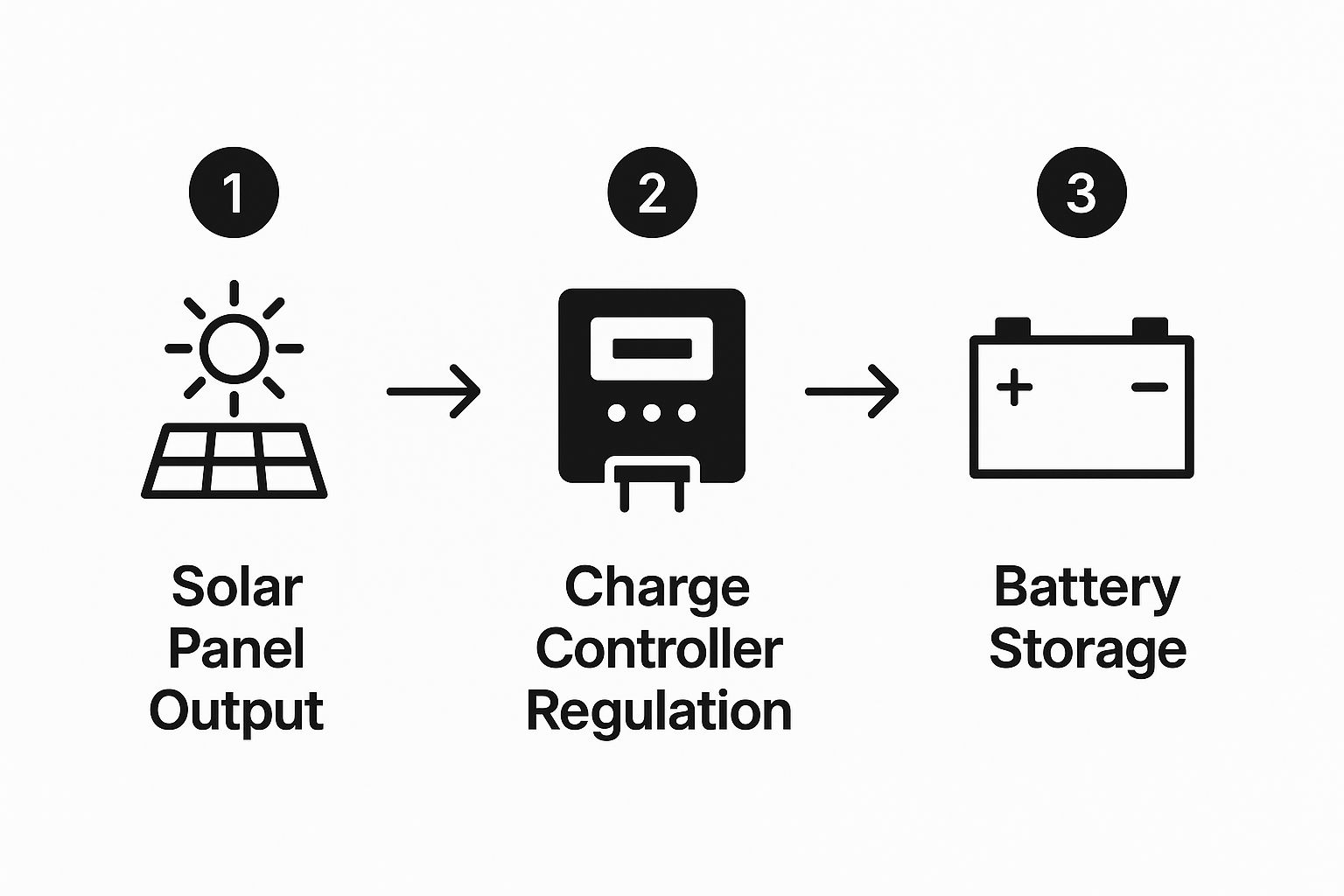
Think of it as a logical journey for every electron generated:
- Generation: Solar panels convert sunlight into direct current (DC) electricity. The voltage they produce fluctuates significantly with solar irradiance.
- Regulation: The solar charge controller is the brain of the DC system. It takes the variable DC output from the panels and converts it to a stable voltage suitable for safely charging the battery, preventing overcharging and extending battery life.
- Storage: The battery bank stores the regulated DC energy. This is the reservoir that provides power during off-sun hours, enabling energy independence. For a deeper dive, check out our complete guide to what an energy storage system is.
- Conversion: The inverter takes the stored DC power from the battery and transforms it into grid-compliant alternating current (AC) power to run loads.
This power flow is the engine driving the massive growth in the solar energy storage market. What was recently valued at over USD 6 billion is now projected to rocket to an incredible USD 48.14 billion by 2034. That boom is a direct result of commercial and residential clients demanding reliable, on-site power—which this exact connection process delivers.
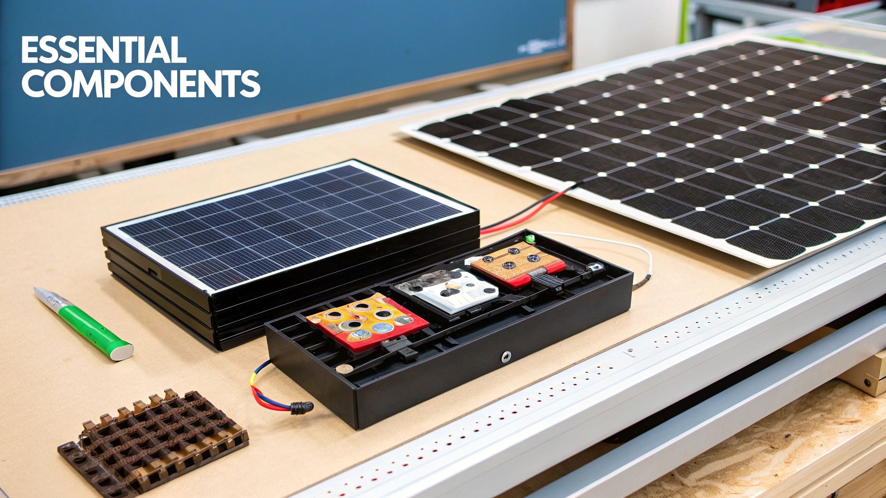
Core Components for a Solar Panel to Battery Connection
Each component has a specific, critical function. Misunderstanding their roles is a common pitfall that leads to improper system design and poor performance.
| Component | Primary Function | Critical Role in System |
|---|---|---|
| Solar Panels | Convert sunlight into DC electricity | The energy source for the entire system. |
| Solar Charge Controller | Regulates voltage and current from panels | Protects the battery from overcharging, maximizing its operational lifespan and safety. |
| Battery Bank | Stores DC energy for later use | Provides power when solar generation is unavailable, ensuring energy resilience. |
| Inverter | Converts DC power from the battery to usable AC power | Makes stored solar energy compatible with standard building loads and appliances. |
| Wiring & Fusing | Safely transmits power between components | Ensures NEC-compliant operation and protects the system from overcurrent faults. |
Critical Mistake to Avoid:
For Installers and Developers: Never design a system around generic components. Before comparing brands like Sungrow or BYD, or pulling out your wire gauge calculator, master this power flow. A mistake at this foundational level puts the entire system's safety and performance at risk. Get the blueprint right, and every subsequent decision will be built on a solid, technically sound base.
Choosing the Right Hardware for Your Project
This is where a project is made or broken. Selecting mismatched or undersized components is a direct path to performance bottlenecks, premature failures, and costly truck rolls. The wrong choice doesn't just cut efficiency; it can create a serious safety hazard.
Your starting point is always the project's objective. Is the client aiming for off-grid resilience, peak demand shaving to reduce commercial energy costs, or maximizing residential self-consumption under a time-of-use rate structure? The answer dictates the sizing and technology of every component you specify.
Sizing Your Core Components
System sizing must be grounded in a thorough load analysis and adhere strictly to the National Electrical Code (NEC). You must calculate the total daily energy consumption in watt-hours, then factor in system inefficiencies and the required days of autonomy.
- Battery Bank: The amp-hour capacity must cover the daily load plus a reserve for low-sun days, accounting for the battery's maximum depth of discharge (DoD).
- Solar Array: The array's total wattage must be sufficient to fully recharge the battery bank within a typical sun day, considering local peak sun hours and seasonal variations.
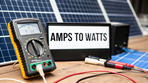
- Charge Controller: The controller's amperage rating must exceed the solar array's short-circuit current (Isc) to handle peak production safely, and its voltage rating must exceed the array's open-circuit voltage (Voc).
In the residential market, battery systems between 3 kW to 6 kW account for over half (54.6%) of revenue, as this range effectively meets typical household energy needs. Lithium-ion, particularly LiFePO4 chemistry, dominates with a 68.1% market share due to superior energy density, long cycle life, and falling costs.
Selecting the Right Technology
Once sizes are determined, specify the technology. For charge controllers, the debate between PWM and MPPT is effectively over for professional applications.
An MPPT (Maximum Power Point Tracking) controller is the industry standard for any serious system. We supply brands like Morningstar because their controllers actively convert excess panel voltage into additional charging current, increasing energy harvest by up to 30%. A simpler PWM (Pulse Width Modulation) controller is only suitable for small, low-voltage, non-critical applications. For a deeper analysis, see our guide on Morningstar solar charge controllers.
Pro Tip for Installers:
Shift the conversation with your clients from upfront cost to lifetime value. LiFePO4 batteries from premier brands like BYD or FranklinWH offer a significantly longer cycle life and a higher depth of discharge than legacy lead-acid technologies. This translates to a lower levelized cost of storage (LCOS) and superior performance over the system's lifetime. Highlighting this ROI is key to winning bids.
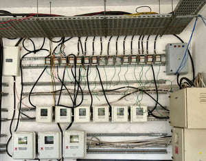
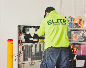
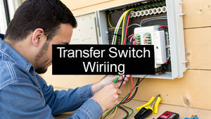
The Hands-On Wiring and Connection Process
You’ve specified and sourced your components. Now it's time to execute the physical installation. This stage demands precision and adherence to a strict order of operations to prevent equipment damage and ensure installer safety. A single mistake, like reversing polarity or connecting in the wrong sequence, can instantly destroy expensive components.
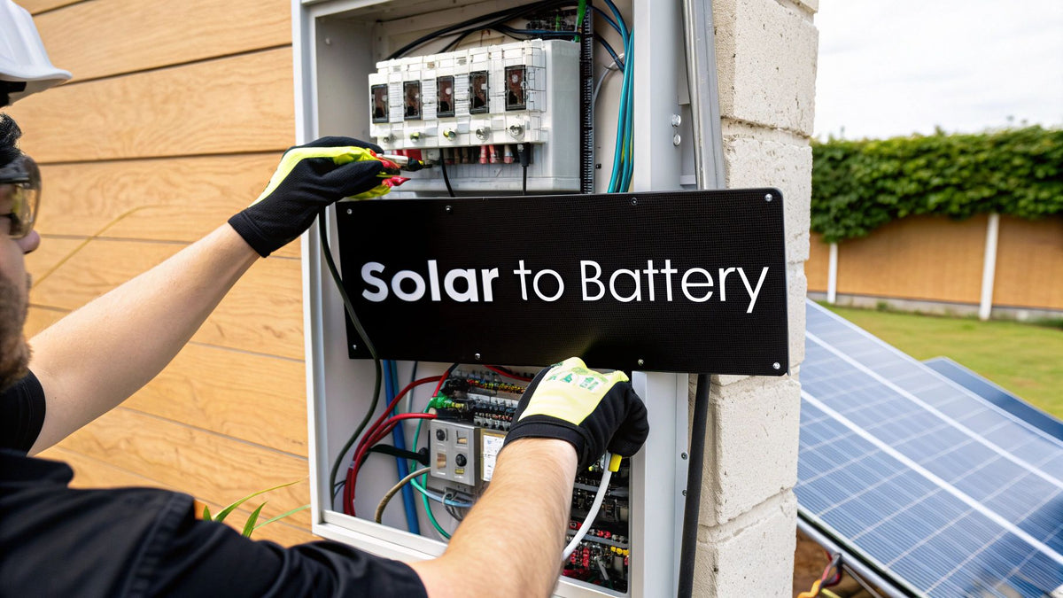
The cardinal rule: always provide the charge controller with a stable voltage reference from the battery before introducing the variable power from the solar panels. This allows the controller to auto-detect the system voltage (12V, 24V, 48V) and configure its charging parameters correctly.
As shown, energy must flow through the charge controller before reaching the battery. This is non-negotiable for regulating power and protecting your client's assets.
Step 1: Connect Battery to Charge Controller
This is the first physical connection you will make. It allows the controller to boot up and recognize the nominal system voltage. Connecting the panels first can confuse the controller, leading it to apply an incorrect charging voltage and permanently damage the battery bank.
- Positive Connection: Run an appropriately sized, color-coded wire from the positive terminal of the battery bank to the positive battery input on the charge controller.
- Negative Connection: Run a matching wire from the battery bank's negative terminal to the controller's negative battery terminal.
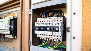
Compliance Watchout:
You must install an NEC-compliant fuse or circuit breaker on the positive line, as close to the battery as possible. This provides critical overcurrent protection and is a non-negotiable code requirement. Failure to do so creates a significant fire hazard.
Step 2: Connect the Solar Array to the Charge Controller
With the controller powered on by the battery, you can now connect the solar array. Before making any connections, ensure the array is de-energized. This can be done by turning off the PV circuit breaker/disconnect or by covering the panels with an opaque blanket to prevent them from generating voltage.
Connect the positive wire from the solar array (or combiner box) to the positive PV terminal on the controller. Then, connect the negative wire to the negative PV terminal. Double-check your polarity with a multimeter. Reversing it will likely cause immediate, irreparable damage to the charge controller. Once connections are verified and torqued, you can energize the PV circuit.
Step 3: Wiring for Voltage and Capacity
The configuration of your solar panels and battery bank—series, parallel, or series-parallel—is a critical design decision that impacts system voltage, current, and efficiency.
| Wiring Configuration | Impact on Voltage | Impact on Amperage/Capacity | Best Use Case |
|---|---|---|---|
| Series | Voltage adds up (V1 + V2...) | Amperage stays the same | Increasing PV array voltage for an MPPT controller to improve efficiency and reduce wire size over long runs. |
| Parallel | Voltage stays the same | Amperage/Capacity adds up (A1 + A2...) | Increasing the total amp-hour capacity of a battery bank or the total current of a PV array without changing the nominal system voltage. |
For most modern systems using MPPT controllers, wiring solar panels in series to achieve a higher PV voltage is standard practice. This lowers the current, allowing for smaller gauge (and less expensive) wire and minimizing voltage drop losses. We cover this in depth in our guide on solar panel wiring basics.
Expert Field Tip:
Always use a calibrated torque wrench or torque screwdriver on all electrical terminals. Every manufacturer provides torque specifications in their installation manuals. Loose connections are the #1 cause of heat, arcing, and catastrophic system failure. This five-minute step prevents major callbacks.
System Commissioning and Safety Protocols

With all components wired, the commissioning phase begins. This is not simply "flipping the switch." It is a methodical process of programming, testing, and verifying every connection to ensure safety, protect the hardware, and maximize the battery's lifespan. Skipping these steps is a recipe for premature failure and voided warranties.
Your first task is to program the solar charge controller with the specific parameters for the installed battery bank. Using default settings is a common and costly mistake.
Programming Critical Charge Parameters
Every battery chemistry has a unique charging profile. A LiFePO4 bank requires different voltage setpoints than a sealed AGM or traditional flooded lead-acid battery. You must input the manufacturer's specified values.
Key parameters include:
- Absorption Voltage: The target voltage for the main charging stage. Setting this too high can cause permanent damage to lithium cells or boil the electrolyte in lead-acid batteries.
- Float Voltage: The maintenance voltage that keeps a fully charged battery topped off without overcharging. Incorrect float settings can lead to sulfation in lead-acid batteries or unnecessary stress on lithium cells.
- Equalization Voltage: A controlled overcharge designed to balance cells and prevent stratification, but it is only for specific types of lead-acid batteries. Never apply an equalization charge to lithium or AGM batteries; doing so will cause catastrophic failure.
Pro Tip for Procurement and Installation:
The battery manufacturer's specification sheet is the authoritative document. Brands like BYD, FranklinWH, or Trojan Battery provide precise setpoints. Using these values is required to maintain the product warranty and ensure UL-listed system safety.
With the controller programmed, perform a final, meticulous safety verification before energizing the system. This is your last chance to confirm every connection is secure and compliant with the National Electrical Code (NEC). Proper equipment grounding is non-negotiable, ensuring a safe path for fault current. Overcurrent protection (fuses and breakers) must be correctly sized for each circuit. All disconnects must be clearly labeled for safe shutdown during maintenance or emergencies.
Essential Safety Checklist Before System Activation
This checklist is your final line of defense. Methodically verify each item before energization. Do not proceed until every point is confirmed.
| Check Point | Verification Method | Importance (Critical/High) |
|---|---|---|
| Correct Polarity | Use a multimeter to confirm positive (+) and negative (-) at all DC connection points. | Critical |
| Torque Specifications | Check all terminal lugs with a calibrated torque wrench against manufacturer specs. | Critical |
| Overcurrent Protection | Confirm correctly sized and rated fuses/breakers are installed on all required circuits. | Critical |
| System Grounding | Visually inspect and use a multimeter to test continuity of the equipment grounding system. | Critical |
| Wire Management | Ensure all wires are secured, protected from physical damage, and have no exposed conductors. | High |
| Disconnects Labeled | Check that all AC and DC disconnects are clearly, legibly, and permanently labeled per NEC requirements. | High |
Once you have confidently verified every item on this list, the system is ready for activation.
Boosting Performance for Longevity and ROI

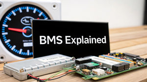
Commissioning the system is a milestone, but true project success is measured by long-term performance and ROI for the client. Proactive monitoring and smart maintenance transform a basic installation into a high-performing asset that delivers value for years. Data from the charge controller and Battery Management System (BMS) are the system's vital signs. Regular monitoring allows you to identify minor issues before they escalate into major failures.
Maximizing Self-Consumption and System Value
A battery's value is realized by intelligently dispatching its stored energy. For commercial and residential clients, two key strategies are critical for reducing utility costs:
- Peak Shaving: Using stored battery power during periods of high grid demand when electricity rates are highest. This is especially effective for commercial clients looking to reduce expensive demand charges.
- Load Shifting: Charging the battery with low-cost or free solar energy during the day and discharging it during evening hours when grid power is more expensive.
These strategies are fundamental to maximizing a client's use of their own generated solar energy. On a larger scale, these same principles enable utility-scale battery systems to provide essential grid services like frequency regulation and backup power, enhancing grid stability and supporting decarbonization efforts, as detailed in recent solar and battery storage market trend analyses.
Interpreting System Data for Proactive Maintenance
The data logs from the charge controller and BMS provide a wealth of performance information. Educating your clients—or offering a service contract—to interpret this data is key to ensuring system longevity.
Expert Insight for Installers:
Train your clients (and your service team) to look for trends, not just daily fluctuations. A single cloudy day will cause a production dip. However, a consistent week-over-week decline in production during sunny conditions is a red flag. It could indicate something simple like soiled panels or a more serious issue like a failing component or a high-resistance connection that requires immediate attention.
By bridging the gap between installation and ongoing performance management, you deliver a solution with measurable, long-term financial benefits. This level of service positions you as a trusted energy partner, not just a contractor.
Common Questions from the Field
Even for seasoned professionals, questions arise on the job site. Here are direct, no-nonsense answers to the most common issues encountered when connecting solar panels to batteries.
Can You Connect Solar Panels Directly to a Battery?
The answer is an unequivocal no. You must never connect a solar panel directly to a battery without a charge controller in between.
A solar panel's voltage fluctuates with sunlight and can easily exceed a battery's safe charging voltage. This will cause severe overcharging, leading to thermal runaway, permanent battery damage, and a significant risk of fire or explosion. The solar charge controller is the essential safety device that regulates voltage and current, protecting the battery and ensuring the system's safe and reliable operation.
What Is the Real Difference Between MPPT and PWM Controllers?
The key differences are efficiency and intelligence. A PWM (Pulse Width Modulation) controller acts as a simple switch, connecting and disconnecting the solar array to prevent overcharging. This method is inefficient as it forces the solar panel to operate at the battery's lower voltage, wasting significant power potential.
An MPPT (Maximum Power Point Tracking) controller is a sophisticated DC-to-DC converter. It constantly tracks the panel's optimal operating voltage and converts the excess voltage into increased charging current. This process can boost energy harvest by up to 30%, especially in colder weather or low-light conditions. For any professional installation, an MPPT controller is the required standard to maximize system ROI.
How Do You Size Wires and Fuses Correctly?
Proper wire and fuse sizing is a critical safety function governed by the National Electrical Code (NEC). The correct wire gauge (AWG) is determined by the maximum circuit current (ampacity) and the length of the wire run (to account for voltage drop).
Using undersized wire for the current load will cause overheating, creating a fire hazard. Using undersized wire for a long run will cause excessive voltage drop, wasting energy. Fuses and circuit breakers are sized to protect the wire, not the load. Their rating must be high enough to handle normal operating current but low enough to trip before the wire's maximum ampacity is exceeded. Always consult NEC ampacity tables and voltage drop calculators.
Field Tip: The Connection Sequence:
To prevent voltage spikes that can damage electronics, always connect in this order:
- Battery to Charge Controller: Powers the controller and allows it to detect system voltage.
- Solar Panels to Charge Controller: Introduces the power generation source.
- Load/Inverter to Battery/Controller: Connects the end-use equipment.
Ready to spec the right components for your next project? Get a full system design and a rapid quote from the experts at PES Supply. We provide the in-stock inventory from leading brands, NABCEP-certified design support, and bundled logistics you need to get the job done right. Request a quote today.
Related Resources:
- Best Solar Panels 2026 — Buyer's Guide
- EG4 vs Tesla Powerwall
- Qcells vs Trina vs JA
- Solar Inverter Buyer's Guide
- Solar Battery Buyer's Guide
- 5kW Solar Kit
- 10kW Solar + Battery Kit
- Off-Grid Cabin Kit
- EG4 Batteries
- Qcells Solar Panels
- Trina Solar
- JA Solar
- REC Solar
- Mission Solar
- Sol-Ark Inverters
- SolarEdge Inverters
- Generac PWRcell
Calculate how much storage you need with our battery sizing calculator.
Check solar incentives available in your state.
Use our free solar system calculator to size your array.
Check out our Solar Panel Comparison Tool. Check out our Inverter Sizing Calculator.
Calculate your solar payback and 25-year savings with our Solar ROI Calculator. Follow our complete DIY solar installation guide for step-by-step instructions. Keep your system running at peak performance with our Solar Maintenance Guide.
Related Resources
- Solar System Calculator
- Battery Sizing Calculator
- Solar Panel Comparison Tool
- Inverter Sizing Calculator
- Solar ROI Calculator
- Solar Installation Guide
- Solar Maintenance Guide
- Solar Permitting Guide
- Battery Installation Guide
- NEC Code Compliance Guide
- Solar Panel Mounting Guide
- Grounding & Bonding Guide
- Solar Incentives by State
- Pro Account — Wholesale Pricing
- PowerLink Network — Contractor Program