Updated September 2026 — refreshed against the live PES catalog; product pricing verified 2026-09-26.
2026 product line update
| Product | Class | Price |
|---|---|---|
| Canadian Solar 710W TOPCon Bifacial Solar Panel | 710W | $340.80 |
| Hyundai 640W 156-Cell TOPCon Bifacial Solar Panel | 640W | $220.78 |
| Thornova Solar TS-BGT72(600) 600W Bifacial Solar Panel | 600W | $165.76 |
| Thornova Solar 595W Solar Panel 144 Cell Bifacial TS-BGT72(595) Wholesale 31 panels per pallet | 595W | $164.64 |
| ZNShine Solar 585W 144-Cell Bifacial Solar Panel | 585W | $246.99 |
| Hyundai HiS-S585OJ 585W Clear on Transparent156 Half-Cell Bifacial Solar Panel | 585W | $195.86 |
Live prices verified 2026-09-26. The current pallet line tops out at 550–640W, plus the Canadian Solar 710W TOPCon flagship panel.
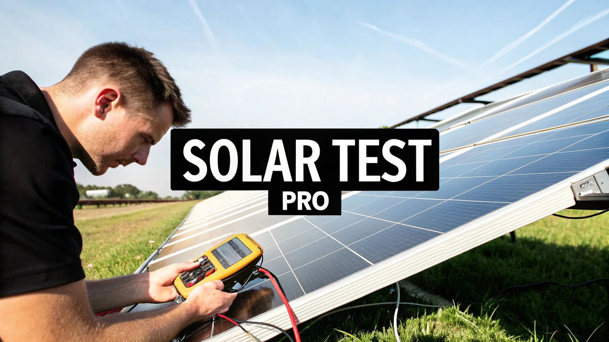
Every underperforming array we've ever been called out to troubleshoot had one thing in common: somebody assumed the panels were fine because the inverter said so. The inverter only tells you what arrives at its terminals. It says nothing about what the modules themselves are capable of producing. If you install, service, or own PV assets, learning to test solar panel output at the module and string level is the single most valuable diagnostic skill you can carry in the truck — and it costs almost nothing beyond a decent meter and twenty minutes of methodical work.

This guide is written for installers, EPC field crews, and asset managers who need numbers they can defend in a warranty claim or an O&M report. We cover the instruments, the exact test sequence, the math that converts a raw multimeter reading into a pass/fail verdict, and the field mistakes that send good techs chasing ghosts. We've pulled this routine on everything from a single Silfab Elite 370W residential module on a garage roof to 400-module commercial strings, and the procedure does not change — only the scale does.
Why Accurate Solar Panel Testing Matters for Your Bottom Line
A module that produces 12% less than its nameplate is not a rounding error. On a 10 kW residential system, that is 1,200 watts of missing capacity the homeowner already paid for. On a 2 MW commercial portfolio, undetected degradation compounds into five figures of lost annual production before anyone opens a warranty file. Manufacturers like Qcells, REC, and Trina warrant power output — typically 85–87.5% of nameplate at year 25 — but they will not pay a claim on a hunch. They want measured data: irradiance, cell temperature, and a normalized power figure.
Testing also protects the installer. We've handed over commissioning reports with module-level Voc and Isc baselines on every job since 2019. When a customer calls three years later claiming the system "died," those baseline numbers settle the conversation in one site visit instead of three. Document everything at commissioning. Your future self will thank you.
The Core Metrics You Must Master
Four numbers define a panel's health. Two you measure with the module disconnected, one you measure under load, and one you calculate:
- Open-circuit voltage (Voc) — module disconnected, leads across positive and negative. Tells you whether all cell strings are intact.
- Short-circuit current (Isc) — module leads shorted through a meter rated for it. Tells you how much current the cells can generate under the present sunlight.
- Operating current (Imp) under load — measured with a DC clamp meter while the string is producing. This is the money number.
- Expected vs. measured power — the calculated comparison that turns readings into a verdict.
Voc and Isc live on the module's datasheet label as STC values: 1,000 W/m² irradiance, 25°C cell temperature, AM 1.5 spectrum. The field never gives you STC. Part of the tester's job is correcting for what the field actually gives you, and we walk through that math below.
Quick-Reference Diagnostic Table: Voc vs. Isc
| Voc Result | Isc Result | Most Likely Cause | Next Step |
|---|---|---|---|
| Normal (±5% of corrected spec) | Normal (±10% of irradiance-corrected spec) | Module healthy | Look downstream: connectors, string wiring, inverter input |
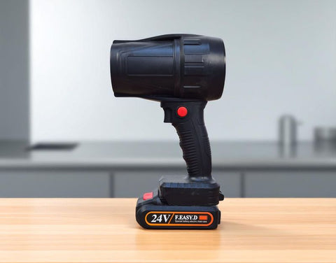
| Normal | Low (>15% below expected) | Soiling, shading, degraded cells, or partial cell cracks | Clean, re-test, inspect with flashlight at low sun angle |
| Low by ~1/3 or ~2/3 | Normal or low | Open bypass diode or dead cell substring | Test diodes in junction box; thermal image under load |
| Zero or near zero | Zero | Open circuit — broken lead, failed junction box, severed cable | Physical trace from module leads to first junction |
| High (> spec at cold temp) | Normal | Normal cold-weather behavior — see NEC 690.7 correction | No fault; verify string Voc stays below inverter max input |
Assembling Your Field Testing Toolkit

You do not need a lab. You need four categories of gear, and the quality of your meter category matters more than everything else combined.
Core Diagnostic Instruments
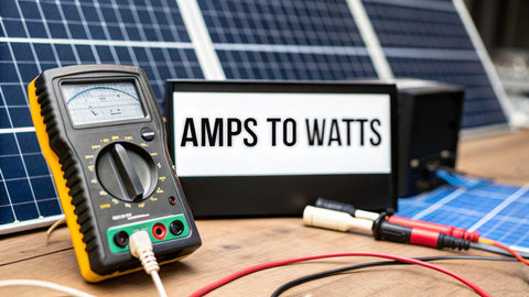
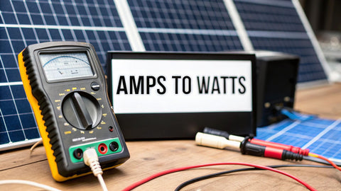
- True-RMS multimeter, CAT III 1000 V or better. This is non-negotiable on modern 1,000 V and 1,500 V strings. We carry a Fluke 87V as the daily driver; it has survived six years of roof work.
- DC-capable clamp meter. Most cheap clamp meters read AC only. For PV you need Hall-effect DC capability — the Fluke 393 FC (CAT III 1500 V) is the industry standard for string work, and its thin jaw fits between rows of MC4 leads.
- Irradiance meter (pyranometer). Without a measured W/m² number, every output calculation is a guess. A handheld solar irradiance meter pays for itself on the first warranty dispute.
- Infrared thermometer or thermal camera. Cell temperature, not air temperature, drives the correction math. Aim at the module backsheet, not the glass.
Tooling Recommendations by Segment
| Crew Type | Voltage Category | Recommended Instruments | Approx. Budget |
|---|---|---|---|
| Residential service tech | CAT III 1000 V | True-RMS DMM, DC clamp meter, IR thermometer | $700–$1,200 |
| Commercial O&M crew | CAT III 1500 V | 1500 V clamp, irradiance meter, thermal camera | $3,000–$6,000 |
| EPC commissioning team | CAT III 1500 V | All of the above plus I-V curve tracer | $10,000–$15,000 |
| Asset manager (audit kit) | CAT III 1000 V | DMM, clamp, irradiance meter — verify contractor data | $1,500–$2,500 |
Non-Negotiable Safety Gear
A PV module is a live generator the moment light hits it. You cannot switch off the sun. Treat every string as energized: Class 0 insulated gloves with leather protectors for any contact with exposed terminals, safety glasses, and a faceshield when working inside combiner boxes. Lock out the inverter AC and DC disconnects before opening anything downstream. We had a tech take a DC arc to a combiner lug in 2022 because a "dead" string was backfed through a shared ground fault path — the arc mark is still on the enclosure door as a reminder. Test like everything is hot, because it is.
Step-by-Step Guide: Testing Solar Panel Output with a Multimeter
This is the exact sequence we train new techs on. Do it in order, and do not skip the irradiance reading.
Step 1: Measure and Record Site Conditions
Before touching a single lead, log three numbers: plane-of-array irradiance (hold the irradiance meter parallel to the module face), backsheet temperature, and the time. These three values make every subsequent reading meaningful. Without them you have trivia, not data.
Step 2: Measuring Open-Circuit Voltage (Voc)
Disconnect the module or string from any load. Set your DMM to DC volts on a range above the expected value. Touch red to positive, black to negative at the module leads or string home-run. A healthy 60-cell-format residential module in bright sun reads near its rated Voc — a 370 W module with a 41.5 V nameplate Voc should show roughly 39–43 V at mild temperatures. Read low? Suspect a bypass diode or a broken cell substring. Read at nameplate or above on a cold morning? That is physics, not a fault — see the NEC 690.7 correction table below.
Step 3: Measuring Short-Circuit Current (Isc)
Set the meter to DC amps on a range above the module's Isc (most residential modules run 10–14 A; check the label). Connect the meter so it shorts the module through its current jack — red lead in the amps jack, never the voltage jack. The module will not be harmed; PV cells are current-limited by design. Compare the reading against the irradiance-corrected expectation: a module rated 11.0 A Isc at STC, measured under 850 W/m², should read close to 11.0 × (850/1000) ≈ 9.35 A. A reading 15% or more below that line after soiling is ruled out means the module is genuinely degraded.
Step 4: Measuring Operating Current Under Load
Reconnect the string and let the inverter return to MPPT operation. Clamp around a single conductor at the combiner or inverter input — never around both conductors of a pair, because the fields cancel and you will read zero. Record string current alongside the irradiance at that exact moment. This Imp reading, compared against the corrected nameplate Imp, is the number warranty departments actually care about.
Step 5: Calculate Expected vs. Measured Output
Run the correction math from the worked examples below and write the percentage next to each module or string ID. Anything within about ±10% of expectation is field-normal. Anything beyond that earns a second visit, a cleaning, or a warranty packet.
The Correction Math That Turns Readings into Verdicts
STC conditions exist on datasheets and almost nowhere else. Two corrections cover 95% of field work: irradiance scaling for current, and temperature correction for voltage and power.
Current scales with irradiance, nearly linearly: Isc(field) ≈ Isc(STC) × (G/1000), where G is your measured W/m².
Voltage moves with cell temperature: crystalline silicon loses roughly 0.28–0.35% of Voc per °C above 25°C and gains it back below. The NEC codifies the cold side of this for design purposes in Table 690.7(A):
| Lowest Expected Ambient (°C) | NEC 690.7(A) Voc Correction Factor | Example: 10 × 41.5 V Module String |
|---|---|---|
| 0 to −4 | 1.10 | 415 V × 1.10 = 456.5 V |
| −5 to −9 | 1.12 | 415 V × 1.12 = 464.8 V |
| −10 to −14 | 1.14 | 415 V × 1.14 = 473.1 V |
| −15 to −19 | 1.16 | 415 V × 1.16 = 481.4 V |
| −20 to −24 | 1.18 | 415 V × 1.18 = 489.7 V |
| −25 to −29 | 1.20 | 415 V × 1.20 = 498.0 V |
| −40 and below | 1.25 | 415 V × 1.25 = 518.8 V |
This table is why string sizing is a winter calculation. A 12-module string that looks comfortable at 500 V on the datasheet can push past a 600 V inverter input limit on a January morning in Minnesota. When you test Voc on a cold day and see numbers above nameplate, check them against this factor before condemning anything — and before congratulating yourself either.
Power correction combines both effects. Expected power at your test conditions:
P(expected) = Pmax(STC) × (G/1000) × [1 + γ × (Tcell − 25°C)]
where γ is the module's power temperature coefficient (typically −0.34 to −0.40 %/°C for mono PERC, closer to −0.29 %/°C for TOPCon and HJT modules like the Qcells XL G11S series and other n-type panels in our solar panel catalog).
Worked Example Table: Expected Output at Real Field Conditions
| Scenario | Irradiance (W/m²) | Cell Temp (°C) | Expected Power, 400 W Module (γ = −0.35%/°C) | Expected Isc, 11.0 A Nameplate |
|---|---|---|---|---|
| STC (datasheet) | 1,000 | 25 | 400 × 1.000 × 1.000 = 400 W | 11.0 A |
| Cool spring morning | 900 | 35 | 400 × 0.900 × [1 − 0.0035×10] = 347.4 W | 11.0 × 0.90 = 9.9 A |
| Hot summer roof | 950 | 65 | 400 × 0.950 × [1 − 0.0035×40] = 326.8 W | 11.0 × 0.95 = 10.45 A |
| Cold bright winter day | 1,050 | 10 | 400 × 1.050 × [1 + 0.0035×15] = 442.1 W | 11.0 × 1.05 = 11.55 A |
| Hazy afternoon | 600 | 45 | 400 × 0.600 × [1 − 0.0035×20] = 223.2 W | 11.0 × 0.60 = 6.6 A |
Look at the hot summer row and commit it to memory: a 400 W panel on a 65°C roof in full sun is honestly a 327 W panel. When a homeowner calls in July saying their system "lost 20%," that is usually thermodynamics, not failure. The winter row is the flip side — modules can legitimately exceed nameplate power in cold, bright conditions, and your string inverter or microinverter fleet will clip the excess.
How to Interpret Your Test Results: A Diagnostic Framework

Raw numbers mean nothing until you slot them into a decision tree. Here is the one we laminate and keep in the truck.
Adjusting for Real-World Conditions
Before declaring any module bad, eliminate the three impostors: soiling (even a thin dust film costs 3–5%), shading (a vent pipe shadow across two cells can crater a whole substring through the bypass diodes), and measurement timing (a cloud edge during your Isc reading invalidates it — retest under stable sky). We once wrote up a "degraded" 24-module string for replacement; the customer's landscaper had been hosing dust into a cement film on the glass. One cleaning later the string tested at 97% of expected. Clean first, condemn second.
A Simple Diagnostic Framework
| Measured vs. Expected | Interpretation | Action |
|---|---|---|
| Within ±10% | Normal field variance | Log baseline, move on |
| 10–15% low | Soiling or early degradation | Clean, retest in 30 days |
| 15–25% low, Voc normal | Cell degradation, PID, or microcracks | Thermal scan; open warranty inquiry with module maker |
| Voc low by ~1/3 or ~2/3 | Bypass diode failure | Test diodes; replace module under warranty |
| Zero Voc and zero Isc | Open circuit | Trace wiring from module to combiner; check MC4 crimps |
Troubleshooting Common Panel Output Issues
Physical Inspection and Obvious Faults
Walk the array before you meter it. Snail trails (brown discoloration lines) signal microcracks. Delamination shows as bubbles or milky patches, usually starting at the edges. Burn marks at the junction box mean heat, and heat means resistance, and resistance on a 10 A string means a fire waiting for a date. Check every MC4 pair you can reach: a half-seated connector is the number one workmanship fault we find on other crews' installs, and it tests as intermittent low current that drives remote monitoring crazy.
Investigating Electrical Connections
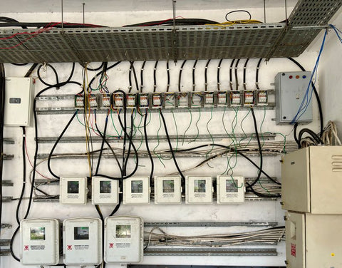
Resistance hides in crimps, lugs, and fuse holders. Torque matters: combiner lugs on 10 AWG PV wire typically spec 15–25 in-lb depending on the manufacturer, and we check every one with a calibrated torque driver at commissioning. A loose lug reads fine at 9 a.m. and fails at solar noon when thermal expansion opens the joint. If your clamp readings wander ±2 A on a clear day, stop blaming the modules and start torquing connections.
Downstream Suspects: Charge Controllers and Inverters
Sometimes the panel tests perfect and the system still underperforms. On battery systems, an undersized or misconfigured controller throttles the array — our guides on charge controller sizing and MPPT vs. PWM selection cover that failure mode in detail. On grid-tied systems, check the inverter's DC input window: a string whose cold-corrected Voc exceeds the max input will never start, and one whose hot Vmp sags below the MPPT minimum will run at reduced efficiency all summer. Hybrid units like the EG4 FlexBOSS21 log per-MPPT string data that makes this diagnosis nearly free — pull the logs before you climb the ladder.
Testing Cadence and Record-Keeping That Holds Up
How often should you test? Our rule of thumb, built from a decade of O&M contracts:
| System Type | Baseline Test | Routine Retest | Trigger-Based Test |
|---|---|---|---|
| Residential grid-tied | At commissioning, every module string | Every 2–3 years | Monitoring shows >10% production drop vs. prior year |
| Commercial rooftop | Commissioning + year 1 | Annually, sample 10–20% of strings | After hail, fire, or reroof work |
| Ground-mount / utility | Full commissioning with I-V curves | Annual I-V sampling per warranty terms | Inverter-level underperformance alarms |
| Off-grid / battery | At commissioning | Annually before winter | Any unexplained generator runtime increase |
Keep the records in a format that survives staff turnover: module ID, string ID, irradiance, cell temp, Voc, Isc, clamped Imp, corrected expected value, and pass/fail. A spreadsheet beats a memory. If you manage off-grid systems with battery banks, pair these electrical baselines with the battery-side discipline in our battery maintenance guide — array problems and battery problems masquerade as each other constantly.
String-Level Testing vs. Module-Level Testing

New techs always ask which level to test first. The answer is top-down: string first, modules only when the string indicts them. Clamping every string at the combiner takes ten minutes on a residential job and instantly tells you whether the problem is one string or a systemic issue like shading or inverter clipping. Only when one string reads low against its neighbors — same roof plane, same tilt, same irradiance — do you start unplugging MC4s to isolate individual modules. Testing 24 modules one by one when the string comparison would have fingered the culprit in minutes is how a one-hour service call becomes a four-hour one.
String Voc comparisons are especially powerful. Ten strings on identical modules should agree within a volt or two under the same sky. One string reading 8% low on Voc has an open diode or a dead substring. One string reading normal Voc but 30% low on clamped current has a resistance problem in its home run, and you should be reaching for the torque driver instead of the ladder.
When to Bring Out the I-V Curve Tracer
A multimeter gives you two points on the curve: Voc and Isc. An I-V curve tracer sweeps the whole curve in seconds and shows you the shape — and the shape is where sneaky faults live. Stepped curves mean bypass diodes are conducting (shading or cracked cells). A depressed knee means series resistance, usually connections. A uniformly shrunken curve with a normal shape means honest degradation or soiling. For warranty claims above a few modules, manufacturers increasingly expect I-V curve data, and a tracer pays for itself the first time it wins a 40-module replacement claim. We resisted buying one for years because of the price; after the first won claim, that hesitation looked silly.
Voltage Drop: The Silent Output Killer Nobody Tests
One more measurement belongs in your routine and almost nobody does it: voltage drop across the DC home runs under load. With the string producing, measure voltage at the combiner and again at the inverter input. The difference should be under 2% of operating voltage — under 1.5% if the designer was generous with copper. We've found 6% drops on 200-foot runs of undersized 12 AWG where the installer saved eighty dollars on wire and cost the owner a panel's worth of production forever. If the drop is high, upsizing the home run or splitting parallel strings beats replacing perfectly healthy modules. Wire sizing follows the same ampacity logic as any NEC 310.16 calculation, and our bus bar and panel capacity guide covers the AC side of that discipline for service equipment.
Questions From the Field
Can I test a solar panel on a cloudy day?
You can, and sometimes you should — Voc readings on overcast days are perfectly valid for finding dead substrings and open diodes, because voltage holds up under low light far better than current does. Isc-based health checks need reasonably stable irradiance above roughly 500 W/m² to be meaningful. Never test between fast-moving clouds; wait for a stable sky or come back another day.
Is it safe to short a solar panel for an Isc test?
Yes, if your meter and leads are rated for the current and voltage. PV modules are current-limited devices; a single residential module shorted through a proper meter runs at Isc harmlessly. What you must never do is short a multi-module string casually — series strings stack voltage into lethal territory, and parallel strings stack current beyond most meter jacks. String-level Isc belongs to clamp meters and I-V curve tracers.
What does it mean if I have voltage but no current?
Normal Voc with collapsed current under load points away from the module and toward the circuit: a tripped string fuse, a failed blocking or bypass diode, a corroded MC4 contact, or a loose combiner lug. The module can generate voltage with no load but cannot push electrons through the resistance. Work the connection chain with a torque driver and contact cleaner before pricing replacement modules.
How accurate does my irradiance meter need to be?
Within ±5% is plenty for field diagnostics, and even a modest handheld unit achieves that. The bigger error source is aim: hold the sensor in the plane of the array, not flat to the sky. A 15° aim error on a tilted roof introduces more error than a cheap sensor ever will.
Should homeowners test their own panels?
Monitoring-app review and visual inspection, yes. Rooftop electrical measurements, no — series-string DC at 400–600 V is unforgiving, and a dropped tool across a junction box can create an arc that does not self-extinguish. Homeowners should call a pro; pros should follow the sequence above and document everything. If you are still vetting a residential installer, ask whether they baseline-test at commissioning. The good ones do.
Related Resources
- Browse residential and commercial solar panels
- Microinverters for module-level power electronics
- String inverters for residential and commercial arrays
- Hybrid inverters for battery-ready systems
- MPPT and PWM charge controllers
- Solar energy system components: the full field guide
- An installer's manual to solar panel system components
- Solar battery sizing for off-grid living
Need pricing or availability on anything in this guide?
Portlandia Electric Supply dropships direct from the manufacturer — most items Ship Direct with lead times stated up front, no surprises.
Get a quote from PESBulk, pallet and contractor pricing available.