A Complete Guide to Solar Cable Connectors for Installers & Developers
For solar installers, EPCs, and project developers, success hinges on mastering the details. While panels and inverters get the attention, the small, often-overlooked solar cable connectors are where project safety, performance, and long-term reliability are truly forged. A single poor connection can trigger underperformance, arc faults, and catastrophic failures, making this a non-negotiable area of focus.
This guide provides the field-proven knowledge you need to select, install, and troubleshoot solar connectors, ensuring every connection is safe, code-compliant, and built to last. We'll cover the critical differences between MC4 and Amphenol H4, break down essential NEC compliance, and provide a step-by-step installation process to eliminate common failures.
Why Solar Cable Connectors Are a Critical Project Decision
The type of solar connector you choose is a decision that echoes through the entire life of a project. They aren't just plastic clips; they are the electrical lifelines that tie every component together. A single point of failure here can knock out an entire string of panels, leading to lost production, expensive service calls, and serious safety risks like arc faults that violate NEC and UL standards.
For any successful project, getting this detail right is non-negotiable.
- For Installers: Specifying the right connector means fewer frustrating callbacks and smoother, code-compliant installations that pass inspection the first time.
- For Developers & EPCs: Selecting the right connector is a core part of managing risk, ensuring system performance meets financial projections, and protecting the project's long-term viability.
The Real-World Impact on Projects
Industry data highlights the critical nature of these components. The global market for photovoltaic solar connectors was valued at around USD 849.26 million in 2024 and is projected to skyrocket to USD 2,459.16 million by 2032. This explosive growth underscores the need for absolute reliability.
However, some industry reports indicate that up to 83% of solar projects encounter connector-related issues, with 3% of those problems leading to complete system shutdowns.
Expert Tip: The Hidden Cost of a Bad Connection
One poorly seated or mismatched connector creates a high-resistance point. This generates intense heat, which can melt the housing, cause an open circuit, and create a legitimate fire hazard. Suddenly, an entire string is down, you're losing production, and you're facing a critical safety failure that could have been avoided with proper component selection and installation.
Tying It All Together for Safety and Performance
Every part of a solar array must work in perfect harmony. While panels and inverters grab the spotlight, it's the humble connector that physically links it all. Understanding the different connector types, their technical specs, and correct installation procedures is fundamental knowledge. They are a core piece of the puzzle, just as important as the other solar panel system components. This guide delivers the practical details needed to make smart procurement decisions that protect your projects, reputation, and bottom line.
When you're out in the field or deep in the design phase, the choice of solar cable connector might seem minor, but it's one of those details that can make or break a project's long-term health. In the U.S. market, this decision often boils down to two heavyweights: the ubiquitous MC4 and the rugged Amphenol H4.
Though they might look similar at a glance, the differences in their locking systems, material makeup, and installation quirks have real-world consequences for your project's timeline and durability.
The demand for these critical components is exploding. The solar connector market is expected to grow from around USD 1,090.8 million in 2025 to a staggering USD 1,823.7 million by 2030. That’s a lot of connections needing to be made, and every single one needs to be reliable.
Choosing the right connector isn't just about what fits; it's about ensuring the integrity of your entire system from day one. Let's get past the spec sheets and into the practical details you actually need.
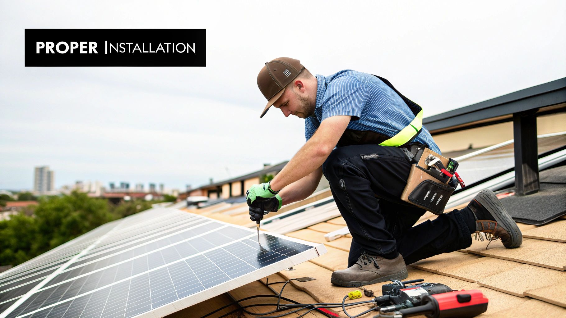
This image really drives home the precision engineering involved in modern connectors. It's a clear reminder that picking the right piece of hardware is fundamental to a solid installation.
Comparison of Common Solar Connector Types
This table breaks down the key specifications of common solar connectors to help you select the right component for your specific project requirements, from residential rooftops to utility-scale solar farms.
| Connector Type | Common Brands | Voltage Rating (VDC) | Current Rating (Amps) | IP Rating | Key Features & Best Use Case |
|---|---|---|---|---|---|
| MC4 | Stäubli (Original), various "MC4-style" clones | 1000V / 1500V | 30A - 50A | IP67 / IP68 | Snap-in lock, requires tool for release. Global industry standard; best for residential/commercial projects where compatibility is key. |
| Amphenol H4 | Amphenol Industrial | 1000V / 1500V | Up to 50A | IP67 / IP68 | Robust locking system. Known for its rugged construction, making it ideal for utility-scale projects and harsh environments. |
| Tyco SOLKLAMP | TE Connectivity | 1000V | 20A | IP68 | Crimp-free design (insulation displacement). Good for rapid field installation, but less common than MC4 or H4. |
| MC3 | Stäubli (Legacy) | 600V | 20A | IP65 | Older, largely obsolete standard. Not NEC compliant for new installations as it can be disconnected without a tool. |
This comparison highlights that while many connectors share similar voltage and current ratings, their locking mechanisms and intended applications can vary significantly.
The MC4 Connector: The Industry Benchmark
If there's one connector that's become synonymous with solar, it's the MC4. Developed by Stäubli (formerly Multi-Contact), it’s the most common connector you’ll find on panels and inverters worldwide. Its ubiquity is its greatest strength.
- Locking Mechanism: The MC4 features a "snap-in" lock that clicks securely into place. Per the National Electrical Code (NEC), it requires a special tool to unlock, a critical safety feature that prevents accidental disconnections under load.
- Ease of Use: Nearly every certified solar installer has worked with MC4s. This widespread familiarity reduces training time and minimizes the risk of installation errors on the job site.
- Material and Durability: Authentic MC4s from brands like Stäubli are made from a tough, UV-resistant polyamide designed to last the 25-year lifespan of a solar array. With an IP67 or IP68 rating, they’re sealed tight against dust and water.
The MC4's market dominance makes it a safe bet for most residential and commercial jobs. However, its popularity has spawned a market flooded with cheap, uncertified knock-offs that can put your entire project at risk.
The Amphenol H4: A Heavy-Duty Alternative
When the project demands maximum durability, many EPCs and developers specify the Amphenol H4. It’s a top-tier choice for large commercial and utility-scale projects where environmental resilience is paramount.
- Locking Mechanism: The H4 connector uses a highly robust locking system, providing a rock-solid connection that withstands high-vibration environments.
- Enhanced Durability: Amphenol utilizes materials engineered for extreme temperature swings and brutal UV exposure, making the H4 a go-to for projects in punishing climates like deserts or coastal areas.
- NEC Compliance: Just like the MC4, the Amphenol H4 is UL-listed and fully compliant with NEC requirements, ensuring it meets the highest U.S. safety standards.
For developers and EPCs overseeing massive solar farms, the H4's reputation for being bulletproof provides that extra peace of mind against the elements.
Compliance Watchout: Mating Dissimilar Connectors
This is a critical point that trips up even experienced teams: NEC 690.33(C) strictly forbids mating connectors from different manufacturers. Clicking an MC4 into an H4—or even an "MC4-style" connector from Brand A into one from Brand B—is a code violation. Mismatched connectors create poor electrical contact, allow moisture ingress, and can lead to dangerous arc faults. This will fail an inspection and could void your warranties. Always procure your mated pairs from a single, trusted source like Portlandia Electric Supply to stay 100% compliant.
Your final decision should hinge on the project's specific needs, system design, and an unwavering commitment to NEC compliance. To see how these components fit into the overall system, take a look at our guide on solar panel wiring basics.
Getting to Know the Key Technical Specs
A connector's spec sheet isn't just a list of numbers—it's the component's vital statistics. These specs define its performance limits, safety boundaries, and suitability for a given project. For anyone installing, designing, or procuring for a solar project, mastering these details is the difference between a system that runs reliably for decades and one that becomes a costly failure point.
Ignoring these specs can lead to mismatched parts, failed inspections, and dangerous conditions like water ingress or arc faults. Let's walk through the most important specs so you can make decisions with confidence.
Voltage Rating: 1000V vs. 1500V
The voltage rating indicates the maximum system voltage a connector can safely handle. While 1000V DC systems were the long-time standard, the utility-scale and large commercial sectors have shifted decisively toward 1500V DC systems to improve project economics.
A 1500V system allows for longer strings of solar panels. This design change reduces the number of combiner boxes, requires less wire, and lowers labor costs, directly improving the project's ROI.
- 1000V DC Connectors: Still the workhorse for residential and smaller commercial projects. They are perfectly suitable as long as the system's maximum voltage stays below the 1000V threshold.
- 1500V DC Connectors: The default choice for large-scale solar farms. Using 1500V-rated connectors on these projects is non-negotiable for safety and code compliance. Installing a 1000V connector in a 1500V system is a serious NEC violation and a major safety risk.
Current Rating (Amps)
The current rating, measured in amps (A), defines how much electrical current a connector can carry continuously without overheating. This value is directly tied to the power output of your panels and the gauge of the solar PV wire being used.
A connector's amp rating must be equal to or greater than the maximum current of the circuit. An undersized connector acts as a bottleneck, causing resistance to build up and generating heat that can melt the plastic housing, creating a fire hazard.
Pro Tip for Procurement: Don't just match the connector's amp rating to the panel's output current. You must also ensure it is rated for the wire gauge being used. A 40A-rated connector crimped onto a wire that can only handle 30A is a critical mismatch that will be flagged during inspection.
IP Rating (Ingress Protection)
The IP rating is one of the most critical specs for any outdoor electrical component. This two-digit code defines how well a connector is sealed against solids (dust, dirt) and liquids (rain, snow, humidity).
Here's the breakdown:
- First Digit (Solids): For solar connectors, this will almost always be '6', indicating the component is completely dust-tight.
- Second Digit (Liquids): This is where you need to pay close attention. An IP67 rating means the connector can be submerged in water up to 1 meter deep for 30 minutes. An IP68 rating means it can survive continuous submersion, with the exact depth and duration specified by the manufacturer.
For any solar installation, IP67 should be the absolute minimum. However, for projects in flood-prone areas or on flat commercial roofs where water may pool, specifying IP68 provides an essential extra layer of defense against moisture—the primary cause of corrosion and dangerous arc faults.
This demand for more resilient components is a significant industry trend. The global solar cable market hit USD 2.3 billion in 2024 and is projected to grow at 8.1% annually through 2034, driven largely by the need for superior environmental resistance.
A Step-by-Step Guide to Crimping and Installing Solar Connectors
https://www.youtube.com/embed/TOtnnAbstDQ
Proper installation is where specifications meet reality. You can select the highest-quality connector, but a single flawed termination renders it useless. This guide is for installers on the ground who need to get it right the first time, every time, to prevent power loss and hazardous failures.
A repeatable, documented process is the key to quality and safety. To ensure every connection is solid and code-compliant, technicians should follow clear Standard Operating Procedures (SOPs). This methodology guarantees every termination meets the stringent standards of the NEC and UL.
Getting Started: Preparation and Cable Stripping
Before crimping, assemble the correct tools: a calibrated crimper with the right die set for your specific connector and wire gauge, a quality wire stripper, and all connector components. Using the wrong tool is the number one cause of failed connections.
- Cut the Cable Cleanly: Start with a clean, square cut on your PV wire. A jagged or angled end will prevent the terminal from seating properly.
- Measure and Strip with Precision: Use a wire stripper to remove the exact length of insulation specified by the connector manufacturer. Too little insulation removed results in a weak crimp; too much risks a short circuit. The conductor should seat fully inside the metal contact pin with zero insulation interfering.
The Make-or-Break Step: Crimping the Metal Contact
A solid crimp creates a cold weld between the wire and the contact pin, forming a durable, low-resistance electrical bond designed to last for decades.
Pro Tip for Every Installer: After every crimp, perform a gentle "pull test." The wire should not move. If it does, the crimp is faulty. Cut it off, use a new contact pin, and repeat the process. An under-crimped connection is a guaranteed failure point.
- Select the Correct Die Set: Your crimping tool has interchangeable dies. Match the die size to both the wire gauge and the specific contact pin. This is non-negotiable.
- Position the Contact: Place the metal contact pin securely into the correct slot in the crimper die, ensuring correct orientation.
- Insert the Wire and Crimp: Slide the stripped wire fully into the contact pin. Squeeze the crimper handles firmly until the tool's ratchet mechanism clicks and releases. This release confirms a complete, uniform crimp.
The Final Assembly: Making it Weatherproof
With the contact securely crimped, the final assembly creates the weatherproof seal that protects the connection from the elements for its entire service life.
- Slide on the Back End First: Before crimping the contact, ensure you've slid the back nut and the rubber bushing (gland) over the wire. Forgetting this common step forces you to cut off a perfectly good crimp.
- Lock the Contact in Place: Insert the crimped pin into its plastic connector housing (male or female). You should hear and feel a distinct click. This confirms it is locked in place and will not back out.
- Tighten and Seal: Screw the back nut onto the connector housing. Tighten it firmly to compress the rubber seal around the wire jacket, creating the watertight seal required for IP67 or IP68 ratings. Use the specified connector wrenches to achieve the correct torque without over-tightening and cracking the plastic threads.
Critical Mistakes to Avoid on the Job
- Using Pliers or Generic Crimpers: This is the #1 cause of failed solar connections. These tools create faulty crimps that will fail inspection and become dangerous hot spots. Always use the manufacturer-specified crimping tool and die set.
- Under-Crimping: Failure to squeeze the crimper until the ratchet releases results in a weak, high-resistance connection that generates heat.
- Improper Sealing: Forgetting to fully tighten the back nut allows moisture ingress, which leads to corrosion and creates a risk for arc faults.
- Using Mismatched Parts: Never mix and match connector housings, pins, or seals from different brands. It is a major safety risk and a direct violation of the NEC.
How to Troubleshoot Common Connector Failures
In the field, a connector failure is a direct hit to energy production and project revenue. For Operations & Maintenance (O&M) teams, quickly identifying and rectifying these issues is critical for minimizing downtime and protecting the asset. Connector failures are almost always caused by poor installation, mismatched components, or environmental damage.
Initial Diagnostic Steps: A Visual Inspection
Before using any tools, perform a thorough visual inspection. This is the fastest and most important first step in diagnosing a problem.
Examine every connection point for these tell-tale signs:
- Signs of Overheating: Discoloration, melted plastic, or charring on the connector body is a red flag for a high-resistance connection, typically caused by a bad crimp or loose terminal.
- Physical Damage: Cracked housings, often from being stepped on or from long-term UV degradation, compromise the weatherproof seal and invite moisture ingress.
- Improper Seating: If connectors are not fully "clicked" and locked together, it creates a weak electrical bond and allows water to seep inside.
- Water Ingress: Any visible moisture, condensation, or corrosion on the metal contacts indicates a failed seal, usually from an improperly tightened back nut.
Note for Field Techs: If you find a burnt or melted connector, do not simply replace it. This is a symptom of a larger issue. You must inspect adjacent connectors and test the entire string to ensure the fault did not cascade and compromise other components.
Pinpointing the Problem With a Multimeter
When a visual check is inconclusive, a multimeter is essential for zeroing in on the exact failure point, whether it's an open circuit or a high-resistance fault.
Testing for Open Circuits
An open circuit means the electrical path is broken, and current flow has stopped. This typically appears in monitoring software as a string producing zero power.
- Safety First: De-energize the system according to your company's lockout/tagout (LOTO) procedures.
- Isolate the String: Disconnect the string's homerun from the combiner box or inverter.
- Check Continuity: Set your multimeter to the continuity setting (audible beep). Test between the positive and negative leads of the string. No beep confirms a break in the line.
-
Isolate the Fault: Starting at one end of the string, disconnect connector pairs and test the continuity of each segment. When you find the segment that fails the test, you have isolated the fault to one of the connectors in that section.
Identifying High-Resistance Connections
A high-resistance connection is more difficult to detect as the string may still produce power, albeit at a reduced level. This fault generates dangerous heat at the connection point.
- Voltage Drop Test: With the system operating under load, carefully measure the voltage at the start and end of the string. A significant voltage drop beyond what is expected from normal line loss indicates a high-resistance problem.
- Thermal Imaging: The most effective method is using a thermal imaging camera. On a sunny day, scan the connectors. A faulty connection will appear as a bright hot spot, instantly revealing the point of high resistance.
By methodically working through these visual and electrical checks, you can confidently identify, repair, and document any solar cable connector failure, restoring system safety and performance.
Your Top Questions About Solar Connectors, Answered
Even seasoned pros have questions about components like solar cable connectors. Getting the details right is non-negotiable for safety, NEC compliance, and long-term performance. Here are the answers to the most common questions we hear from the field.
Can You Mix and Match Different Brands of MC4 Connectors?
Absolutely not. This is one of the most critical safety rules in the solar industry. The National Electrical Code (NEC) 690.33(C) is unambiguous: you cannot mate solar connectors from different manufacturers, even if they appear to be "MC4-style."
Each manufacturer uses proprietary molds, materials, and tolerances. Mating dissimilar brands creates a weak link that leads to serious problems:
- High Resistance: A poor fit causes electrical resistance, which generates intense heat, creating a fire hazard that can melt the housing.
- Water Intrusion: An imperfect seal allows moisture to penetrate, leading to corrosion, ground faults, and dangerous arc faults.
- Failed Inspections: An inspector will immediately spot mismatched connectors, flagging the installation for a code violation and halting the project.
Pro Tip for Ordering: The simplest way to ensure compliance is to always purchase male and female connectors as a complete, mated pair from the same trusted supplier. This guarantees a UL-listed, 100% compliant connection right out of the box.
What’s the Real-World Lifespan of a Solar Connector?
A high-quality connector from a Tier 1 brand like Stäubli or Amphenol, when installed correctly, is designed to last the entire 25 to 30-year life of the solar system.
However, this longevity depends on two critical factors:
- Workmanship: The crimp must be perfect, made with the manufacturer-specified tool for that specific connector. The connection must also be fully seated and sealed against the elements.
- Material Quality: The connector must be made from high-grade, UV-stable polyamide. Cheap, uncertified knock-offs often use inferior plastics that become brittle and crack after just a few years of sun exposure, creating a system failure point.
How Tight Is "Tight Enough" for a Connector?
The goal is to tighten the back nut enough to fully compress the internal rubber grommet, creating a critical watertight seal around the wire jacket. This is often described as "wrench tight."
The best practice is to use the plastic disconnect wrenches supplied by the connector manufacturer. They provide the correct leverage to achieve a snug, weatherproof seal without damaging the component. Using channel locks or other tools risks over-tightening, which can crack the housing or strip the threads, immediately voiding its IP rating.
For the main connection between the male and female parts, listen for the satisfying "click" that confirms it is fully seated and securely locked.
At Portlandia Electric Supply, we provide the compliant, top-tier solar cable connectors that installers, EPCs, and developers trust for building safe, high-performance projects. We offer real in-stock inventory and bundled logistics to ensure you get the right components on time, every time. Get a Bulk Quote Today.