Updated September 2026 — refreshed against the live PES catalog; product pricing verified 2026-09-26.
2026 product line update
| Product | Class | Price |
|---|---|---|
| Canadian Solar 710W TOPCon Bifacial Solar Panel | 710W | $340.80 |
| Hyundai 640W 156-Cell TOPCon Bifacial Solar Panel | 640W | $220.78 |
| Thornova Solar TS-BGT72(600) 600W Bifacial Solar Panel | 600W | $165.76 |
| Thornova Solar 595W Solar Panel 144 Cell Bifacial TS-BGT72(595) Wholesale 31 panels per pallet | 595W | $164.64 |
| ZNShine Solar 585W 144-Cell Bifacial Solar Panel | 585W | $246.99 |
| Hyundai HiS-S585OJ 585W Clear on Transparent156 Half-Cell Bifacial Solar Panel | 585W | $195.86 |
Live prices verified 2026-09-26. The current pallet line tops out at 550–640W, plus the Canadian Solar 710W TOPCon flagship panel.
⏱️ Reading time: 16 minutes | Updated July 2026
Solar Charge Controller Sizing and Selection Guide (2026)
📋 Key Takeaways
- Charge controller current rating must handle the array's maximum output with a 25% safety margin.
- Controller voltage must exceed the battery bank's nominal voltage.
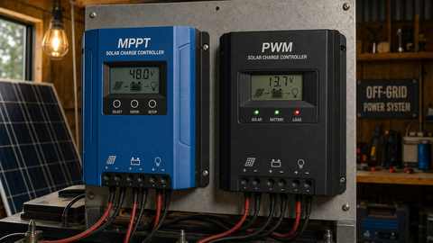
- MPPT controllers offer 20-30% more energy harvest than PWM in most systems.
- NEC requires charge controllers to be sized for short-circuit current (Isc) multiplied by 1.25.
- Temperature derating is essential for controllers installed in hot environments.
I've replaced more fried charge controllers than I care to count, and almost every one died from a sizing mistake made on paper months earlier — never from a factory defect. Charge controllers are the unsung workhorses of off-grid and battery-based solar systems. A correctly sized charge controller protects your battery investment, maximizes energy harvest, and ensures years of trouble-free operation. An undersized controller will trip offline during peak production, while an oversized one wastes money and may never reach its optimal operating range. This 2026 guide provides installers and system designers with the formulas, code references, and brand-specific recommendations needed to select and size the right charge controller for any application.
Browse our full selection of charge controllers from industry-leading brands, and pair them with our solar panels for a complete off-grid solution. Standard delivery is 7-10 business days.
Charge Controller Sizing Fundamentals
Sizing a solar charge controller comes down to two primary calculations: the controller's current rating (amps) must handle the maximum array output, and its voltage rating must exceed the array's maximum open-circuit voltage at the coldest expected temperature. Get either of these wrong and you risk equipment damage, fire, or voided warranties.
The Core Sizing Formula
Controller Current Rating ≥ (Array Wattage / Battery Bank Voltage) × 1.25
The 1.25 safety factor accounts for edge-of-cloud enhancement, where irradiance can briefly exceed 1,000 W/m² by 25% or more. This is consistent with NEC 690.8(A)(1), which requires PV circuits be sized at 125% of short-circuit current. For charge controllers specifically, most manufacturers also recommend adding a second 25% margin for continuous operation, bringing the total derating to 1.56 (1.25 × 1.25).
Conservative sizing: Controller Rating ≥ (Array Wattage / Battery Voltage) × 1.56
For example, a 1,500 W array charging a 24 V battery bank: 1,500 / 24 = 62.5 A. With the 1.25 factor: 62.5 × 1.25 = 78.1 A. With the full 1.56 factor: 62.5 × 1.56 = 97.5 A. You would select a controller rated for at least 80 A (with the 1.25 factor) or 100 A (with the conservative 1.56 factor).
Step-by-Step Sizing Process
- Step 1: Determine the total array wattage (sum of all panel nameplate ratings).
- Step 2: Identify the battery bank nominal voltage (12 V, 24 V, or 48 V).
- Step 3: Calculate the charge current: Array Watts / Battery Voltage.
- Step 4: Apply the derating factor: multiply by 1.25 (NEC minimum) or 1.56 (conservative).
- Step 5: Calculate the maximum array voltage at record-low temperature (see next section).
- Step 6: Select a controller whose voltage rating exceeds the calculated maximum and whose current rating meets or exceeds the calculated current.
Sizing Quick Reference: Array Watts to Controller Amps
Run the formula once and you'll see it collapses into a lookup table for common configurations. Values below use Charge Current = Array Watts ÷ Battery Voltage, then apply the NEC 1.25 factor and the conservative 1.56 factor. Always round the controller rating up from the column that matches your risk tolerance.
| Array size | Battery bank | Base charge current | NEC minimum (×1.25) | Conservative (×1.56) | Typical controller choice |
|---|---|---|---|---|---|
| 400 W | 12 V | 33.3 A | 41.7 A | 52.0 A | 45–60 A class |
| 1,000 W | 12 V | 83.3 A | 104.2 A | 130.0 A | 100 A class — consider 24 V instead |
| 1,000 W | 24 V | 41.7 A | 52.1 A | 65.0 A | 60 A class |
| 1,500 W | 24 V | 62.5 A | 78.1 A | 97.5 A | 80–100 A class |
| 2,400 W | 48 V | 50.0 A | 62.5 A | 78.0 A | 60–80 A class |
| 3,000 W | 48 V | 62.5 A | 78.1 A | 97.5 A | 80–100 A class |
| 6,000 W | 48 V | 125.0 A | 156.3 A | 195.0 A | Two 80–100 A controllers or a 200 A unit |
The last row makes the case for splitting big arrays across two controllers: two 80 A units give you redundancy (one failure doesn't kill charging) and often cost less than a single 200 A chassis. Dual-MPPT units like the MidNite Barcelona 200A put both trackers in one box for exactly this scenario.
Array Voltage Matching
The worst service call I ever took was a 150 V controller wired to a string that hit 163 V on a bluebird January morning at -22°C. The unit didn't trip; it failed, and it took the monitoring board with it. The charge controller's maximum PV input voltage must exceed the array's open-circuit voltage at the lowest expected temperature. This is the same principle that governs string inverter sizing, and it is governed by NEC 690.7.
Voltage Calculation at Cold Temperature
V_oc_max = N_panels × V_oc × (1 + α × (25 - T_min))
Where α is the temperature coefficient of Voc (typically 0.003/°C or 0.30%/°C), and T_min is the record-low ambient temperature in °C.
Example: A 6-panel series string with V_oc = 45.6 V per panel, installed where temperatures can drop to -20°C:
V_oc_max = 6 × 45.6 × (1 + 0.003 × (25 - (-20))) = 273.6 × (1 + 0.135) = 273.6 × 1.135 = 310.5 V
The selected controller must have a maximum PV input voltage exceeding 310.5 V. A 150 V controller would fail catastrophically; a 250 V controller would still be insufficient. You would need a controller rated for at least 350 V, or reconfigure the array into shorter strings.
Controller Voltage Classes
| Controller Voltage Class | Max PV Input Voltage | Typical Application |
|---|---|---|
| 12V/24V auto-sensing | 50 - 75 V | Small 12V systems, RVs, boats |
| 12V/24V/48V | 100 - 150 V | Residential off-grid, small cabin systems |
| Mid-voltage MPPT | 150 - 250 V | Larger off-grid systems, series strings |
| High-voltage MPPT | 250 - 600 V | Commercial off-grid, high array voltage |
| Industrial MPPT | 600+ V | Utility-scale battery charging, microgrid |
Current Ratings and Continuous Duty
Charge controller current ratings represent the maximum continuous output current the device can handle at a specified ambient temperature (usually 25°C or 40°C depending on the manufacturer). Two factors must be checked against this rating.
Array Short-Circuit Current
Per NEC 690.8(A)(1), the PV source circuit current is 1.25 × Isc of the array. For parallel strings, sum the Isc values of all strings before applying the factor. The controller must be rated for this current, or you must add an overcurrent protection device to limit it.
Example: 3 parallel strings, each with Isc = 10.2 A. Total Isc = 30.6 A. NEC current = 30.6 × 1.25 = 38.25 A. With the additional 1.25 continuous factor: 38.25 × 1.25 = 47.8 A. Select a controller rated for at least 50 A.
Charge Current to Battery
The controller's output current to the battery bank is determined by the maximum power point of the array and the battery voltage. For MPPT controllers, the output current can be higher than the input current because the controller steps down voltage and increases current proportionally (minus efficiency losses).
I_charge = (Array Watts × MPPT Efficiency) / Battery Voltage
For a 3,000 W array with 98% efficient MPPT charging a 48 V bank: I_charge = (3,000 × 0.98) / 48 = 61.25 A. The controller must be rated for this output current continuously.
Breaker and Overcurrent Protection Sizing
Proper breaker sizing between the charge controller, battery, and array is essential for code compliance and equipment protection. NEC 690.9 requires overcurrent protection on all PV circuits, and NEC 690.10 specifies additional requirements for stand-alone systems.
PV Input Breaker (Array to Controller)
The PV input breaker must be sized at 156% of the array's short-circuit current (NEC 690.8 combined factors) and must not exceed the controller's maximum input current rating.
Breaker_size ≥ Isc_total × 1.56
Round up to the next standard breaker size. For Isc_total = 30.6 A: 30.6 × 1.56 = 47.7 A. Select a 50 A DC breaker rated for the system's DC voltage.
Battery Output Breaker (Controller to Battery)
The battery-side breaker protects the controller and wiring from reverse current and fault conditions. Size it at 125% of the controller's rated output current.
Battery_breaker ≥ Controller_rating × 1.25
For a 60 A controller: 60 × 1.25 = 75 A. Select an 80 A DC breaker.
Load Output Breaker (Controller to DC Loads)
If the controller has a load terminal for DC loads, the load breaker is sized at 125% of the load terminal's rated current. This protects the controller's load output circuit from overload.
Breaker Sizing Summary Table
| Breaker Location | Sizing Formula | Code Reference |
|---|---|---|
| PV input (array to controller) | Isc × 1.56, round up to standard size | NEC 690.8, 690.9 |
| Battery output (controller to battery) | Controller rated current × 1.25 | NEC 690.10, 690.9 |
| Load output (controller to DC loads) | Load terminal rating × 1.25 | NEC 690.10 |
| Between parallel battery strings | Per battery manufacturer spec | NEC 690.71, 480.4 |
Top Charge Controller Brands for 2026
Victron Energy
Victron's BlueSolar and SmartSolar MPPT charge controllers are the gold standard for off-grid and marine applications. The SmartSolar series includes built-in Bluetooth for monitoring and configuration via the VictronConnect app. Key models include the SmartSolar MPPT 100/30 (30 A, 100 V max) for small systems and the SmartSolar MPPT 250/100 (100 A, 250 V max) for large off-grid arrays. Victron controllers feature ultra-fast MPPT tracking that improves energy harvest by up to 30% compared to slower tracking algorithms, particularly during rapidly changing cloud conditions. Their wide input voltage range and robust thermal management make them suitable for harsh environments.
MidNite Solar
MidNite Solar's Classic series MPPT controllers are engineered for the demanding conditions of North American off-grid installations. The Classic 150 (150 V max, 96 A output), Classic 200 (200 V max, 79 A output), and Classic 250 (250 V max, 63 A output) cover a wide range of system sizes. MidNite Solar controllers include features specifically designed for the installer: built-in arc fault circuit interruption (AFCI), ground fault detection, an integrated web server for remote monitoring, and a unique "sweep" function that tracks the maximum power point across partial shading conditions. The Kid series offers a compact 30 A MPPT controller ideal for small off-grid and RV systems.
EPEver
EPEver (formerly EPever) offers cost-effective MPPT and PWM charge controllers popular in budget-conscious installations and DIY solar projects. The Tracer AN series (10 A to 40 A, 100 V to 150 V max) provides reliable MPPT tracking at a fraction of the cost of premium brands. The Tracer BN series adds an LCD display and expanded battery chemistry support including lithium iron phosphate (LiFePO4). While EPEver controllers lack some advanced features of Victron and MidNite Solar (no built-in Bluetooth on most models, simpler fault protection), they deliver solid performance for small to medium off-grid systems where budget is the primary constraint.
Morningstar
Morningstar Corporation has built a reputation for extreme reliability, with many controllers in continuous service for 20+ years. The TriStar MPPT 600V (600 V max, 45-60 A output) is designed for high-voltage arrays and industrial applications, while the TriStar TS-MPPT-60 (150 V max, 60 A) covers standard off-grid systems. The SunSaver MPPT (15-30 A) is a compact controller for small systems and remote applications. Morningstar controllers feature military-grade components, conformal-coated circuit boards, and a 5-year warranty (extendable to 10 years). Their TriStar controllers include advanced battery charging algorithms for flooded, gel, AGM, and lithium batteries, with programmable custom charge profiles.
Brand Comparison Summary
| Brand | MPPT Top Model | Max Current | Max Voltage | Best For |
|---|---|---|---|---|
| Victron Energy | SmartSolar MPPT 250/100 | 100 A | 250 V | Premium off-grid, marine, mobile |
| MidNite Solar | Classic 150 | 96 A | 150 V | North American off-grid, harsh environments |
| EPEver | Tracer AN 40A | 40 A | 150 V | Budget systems, DIY solar |
| Morningstar | TriStar TS-MPPT-60 | 60 A | 150 V (600V model available) | Industrial, remote critical systems |
Pairing the controller with the right bank size matters as much as chemistry. Our solar battery sizing guide runs the kWh and amp-hour math, and the battery storage collection covers the LFP banks these controllers charge.
Battery Chemistry Considerations
The charge controller must support the battery chemistry in your system. Modern controllers offer programmable charge profiles for different battery types, but the specifics matter.
- Flooded lead-acid: Requires multi-stage charging (bulk, absorption, float) with temperature compensation of -4 to -5 mV/°C/cell. Equalization cycles needed periodically.
- AGM/Gel: Similar multi-stage charging but with lower float voltages. No equalization for gel batteries.
- Lithium iron phosphate (LiFePO4): Requires constant-current/constant-voltage (CC/CV) charging with no float stage. The controller must support BMS communication (CAN bus or RS485) for safe lithium charging. Many modern controllers from Victron and MidNite Solar offer native LiFePO4 profiles.
Verify that the controller's charge algorithm matches your battery manufacturer's specifications. Using a flooded lead-acid profile on lithium batteries can damage the BMS and create a fire hazard.
Temperature Compensation
Battery charging voltage changes with temperature. A charge controller without temperature compensation will overcharge batteries in hot conditions and undercharge them in cold conditions, reducing battery life by 20-40%. All quality controllers include a remote temperature sensor (RTS) that mounts on the battery terminal and communicates the actual battery temperature to the controller. For lithium batteries, temperature compensation is less critical but still recommended to prevent charging below freezing (0°C), which can cause lithium plating and permanent damage.
Sizing Example: Complete Off-Grid System
System Parameters
- Array: 6 × 400 W panels = 2,400 W total
- Panel specs: V_oc = 45.6 V, V_mp = 37.8 V, Isc = 10.5 A
- Battery bank: 48 V LiFePO4, 200 Ah
- Site: Denver, CO, record-low -25°C
- String configuration: 3 strings of 2 panels in series (parallel)
Voltage Check
Cold V_oc per panel: 45.6 × (1 + 0.003 × (25 - (-25))) = 45.6 × 1.15 = 52.4 V. Two panels in series: 52.4 × 2 = 104.8 V. Select a controller with at least 150 V max input voltage.
Current Check
Total Isc (3 parallel strings): 10.5 × 3 = 31.5 A. NEC current: 31.5 × 1.25 = 39.4 A. Continuous duty: 39.4 × 1.25 = 49.2 A. Select a controller rated for at least 50 A.
Charge Current Check
Charge current = (2,400 × 0.98) / 48 = 49.0 A. Consistent with the NEC calculation above.
Controller Selection
A MidNite Solar Classic 150 (150 V, up to 96 A at 48 V) or a Morningstar TriStar TS-MPPT-60 (150 V, 60 A) would both be appropriate. The Classic 150 provides more headroom for future array expansion, while the TriStar 60 is more cost-efficient for the current array size.
Breaker Sizing
- PV input breaker: 31.5 × 1.56 = 49.1 A → 50 A DC breaker (150 V rated)
- Battery output breaker: 60 × 1.25 = 75 A → 80 A DC breaker (80 V rated)
- Load output breaker: depends on load sizing, typically 20-30 A
We keep a small shelf in the shop of dead controllers customers have brought in over the years. Every one of them maps to a mistake in the list below — most often the cold-voltage miss, occasionally the skipped temperature sensor.
Common Selection Mistakes
- Sizing for STC only: Always apply NEC 690.8 derating factors. A controller sized at exactly the STC current will trip offline under edge-of-cloud conditions.
- Ignoring cold-temperature voltage: A controller that works fine in summer may fail catastrophically on the first cold winter morning when Voc rises above its rating.
- Mixing battery chemistries: Using a controller without a LiFePO4 profile on lithium batteries is dangerous. Always verify chemistry compatibility before purchase.
- Skipping the temperature sensor: Operating without an RTS on lead-acid batteries will significantly reduce battery life and void most battery warranties.
- Undersizing wire between controller and battery: The controller-to-battery connection carries the highest current in the system. Use appropriately sized wire (typically 2/0 AWG or larger for 60+ A controllers) to minimize voltage drop and heat.
Conclusion
Properly sizing a solar charge controller requires careful attention to array voltage at temperature extremes, current ratings with NEC derating, breaker selection per code, and battery chemistry compatibility. By following the formulas and processes outlined in this guide, you can confidently select a controller from brands like Victron, MidNite Solar, EPEver, or Morningstar that will maximize energy harvest and protect your battery investment for years to come.
Shop our complete selection of MPPT and PWM charge controllers from leading manufacturers. Pair them with our solar panels and inverters for a complete system solution. All orders from PES Supply ship within 7-10 business days.
Shop This Article
Ready to specify equipment for your next project? PES Supply stocks 50,000+ SKUs from 169 authorized brands with delivery in 7–10 business days. Here are our top picks based on the topics discussed above:
- Morningstar GenStar 60A MPPT (GS-MPPT-60M) — 98% tracking, 150V input, residential/commercial
- Morningstar ProStar 15 Gen3 (PS-15) — PWM controller, small off-grid
- Schneider SW 4024 w/ MPPT 60-150VDC — 4kW inverter + charge controller
- Schneider SW 4048 w/ MPPT 60-150VDC — 4kW 48V inverter + controller
- MidNite Barcelona 200A MPPT — 600V input, 48V, dual MPPT, commercial
Browse our complete selection: Charge Controllers | Inverters | Solar Panels
Frequently Asked Questions
How do I size a solar charge controller?
Calculate the array's short-circuit current (Isc) multiplied by the number of parallel strings, then apply a 1.25 NEC safety factor and a 1.25 continuous load factor. The controller's current rating must exceed this value. Also ensure the voltage rating exceeds the battery bank nominal voltage.
What size charge controller do I need for a 400W solar panel?
A typical 400W panel has an Isc of about 10-14A. With the 1.25 NEC factor and 1.25 continuous factor, you need a controller rated for at least 16-22A. A 30A MPPT controller is a common choice for a single 400W panel system.
Do I need a bigger charge controller for cold climates?
Yes. Solar panels produce higher voltage and current in cold conditions. The charge controller must handle the cold-weather Isc and Voc to avoid tripping offline or sustaining damage during winter peak production.
Can I connect multiple charge controllers to one battery bank?
Yes, multiple charge controllers can charge the same battery bank, which is common in systems with arrays on different roof orientations. Each controller manages its own array independently, and the battery bank receives the combined charging current.
What happens if my charge controller is undersized?
An undersized controller will trip offline during peak production, limiting current to protect itself. This wastes energy and may prevent the battery from fully charging on sunny days. Chronic overloading can also reduce controller lifespan.
Related Articles
- MPPT vs. PWM Charge Controllers: Which One Do You Need?
- Solar Charge Controller Sizing and Selection Guide (2026)
Ready to Source Your Equipment?
Browse 50,000+ SKUs from 169 authorized brands. Trade pricing with full OEM warranties.
Shop All Categories Request a Quote