How to Extend Solar Battery Life: Maintenance Tips and Best Practices
Depth of discharge, temperature management, charge rates, and the maintenance calendar that adds years to lithium and lead-acid storage — with the math that proves it.
A lithium battery bank is the most expensive line item in most residential storage systems, and it's also the component whose lifespan is almost entirely determined by how it's treated. The same 10 kWh battery can deliver 4,000 cycles or 8,000 cycles depending on decisions the installer made on day one and habits the owner keeps for the next decade. That spread is the difference between replacing the bank in year 8 and still running it in year 15.
We handle warranty traffic for thousands of batteries a year across lithium, Fortress, Pytes, and EG4 lines, plus legacy lead-acid banks from MK Battery. The failure patterns are remarkably consistent — and mostly preventable. This guide distills what actually moves cycle life: depth of discharge, temperature, charge/discharge rates, storage habits, and a maintenance calendar you can hand to customers.
My own bias, from years of reading RMA reports: heat and deep discharge kill more batteries than every other cause combined, and both are installation choices, not manufacturing defects. Get those two right and the rest of this article is refinement.
The Chemistry Baseline: What You're Maintaining
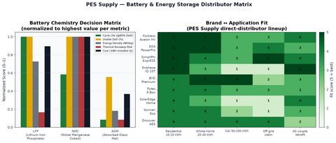
Maintenance strategy depends on chemistry. Lithium iron phosphate (LFP) dominates new residential storage; lead-acid (flooded and AGM) persists in legacy off-grid; nickel-based lithium (NMC) lives on in older Tesla-era packs. Their care instructions differ in ways that matter:
| Parameter | LFP (LiFePO4) | AGM lead-acid | Flooded lead-acid |
|---|---|---|---|
| Rated cycle life @ 80% DoD | 4,000 – 6,000 | 500 – 800 | 1,000 – 1,500 |
| Rated cycle life @ 50% DoD | 6,000 – 10,000 | 800 – 1,200 | 1,800 – 2,500 |
| Recommended routine DoD | 80 – 90% | 50% | 50% |
| Max continuous charge rate | 0.5C (1.0C for many rack units) | 0.2C | 0.15 – 0.2C |
| Float/idle behavior | No float needed; hold 50–60% for storage | Float 13.4–13.8 V (12 V bank) | Float 13.2–13.6 V + equalize monthly |
| Calendar life (typical) | 15 – 20 yr | 5 – 8 yr | 6 – 10 yr |
| Watering / venting | None | None (sealed) | Monthly watering, vented hydrogen |
The takeaway for mixed fleets: lead-acid wants to live between 50% and 100% state of charge and hates being left discharged; LFP is happiest between 10% and 90% and hates being left at 100% in the heat. They are nearly opposite animals, and the fastest way to kill a new LFP retrofit is to leave it programmed to the old lead-acid charge profile.
Depth of Discharge: The Biggest Lever
Cycle life scales with how deep you cycle. The relationship isn't linear — cycling to 100% DoD doesn't cost twice as much life as 50%; it costs three to four times as much. Here's the working table we use when advising customers on reserve settings:
| LFP daily DoD | Approx. cycle life | Years at 1 cycle/day | Usable energy per 10 kWh bank |
|---|---|---|---|
| 100% | ~3,000 | ~8.2 yr | 10.0 kWh |
| 90% | ~4,500 | ~12.3 yr | 9.0 kWh |
| 80% | ~6,000 | ~16.4 yr | 8.0 kWh |
| 60% | ~8,000 | ~21.9 yr | 6.0 kWh |
| 50% | ~10,000 | ~27.4 yr (calendar life limits first) | 5.0 kWh |
Notice the trade: moving from 100% to 80% DoD surrenders 2 kWh of daily throughput and doubles calendar-adjusted lifespan. For most grid-tied backup customers, the right setting is 80–90% usable with a 10–20% reserve floor — which is why the 20/80 battery rule has become the industry shorthand for longevity-first programming. Off-grid customers who genuinely need every watt-hour should size a larger bank and cycle it shallower rather than flogging a small one; our off-grid sizing guide and battery bank sizing guide walk through that arithmetic.
Temperature: The Silent Lifespan Thief
Every battery datasheet lists an operating range; few owners read the lifespan implications. The Arrhenius rule of thumb: sustained operation 10°C above the 25°C reference roughly doubles the rate of calendar-aging reactions. A battery living at 35°C ages about twice as fast as one at 25°C. At 45°C — a number we routinely see inside unconditioned garage installs in July — aging is three to four times the reference rate.
| Sustained ambient temperature | Relative calendar-aging rate (LFP) | Practical guidance |
|---|---|---|
| 0 – 10°C | 0.5 – 0.7× | Slows aging but blocks charging below 0°C — BMS will refuse; needs heating below freezing |
| 15 – 25°C | 1.0× (reference) | Ideal band; conditioned space, insulated garage, or shaded exterior cabinet |
| 25 – 35°C | 1.5 – 2× | Acceptable with airflow; add ventilation to enclosures |
| 35 – 45°C | 2 – 4× | Avoid for permanent install; relocate or actively cool |
| > 45°C sustained | > 4× | Warranty risk; BMS derating; expect early capacity loss |
Placement rules we give every installer: never west-facing exterior walls in hot climates; never unconditioned metal sheds in the Sun Belt; respect the manufacturer's clearance spec (usually 4–12 inches around rack batteries) because stacked units heat-soak each other; and in cold climates, buy batteries with built-in heating or put them in conditioned space. I've seen a beautiful $30,000 bank mounted in an Arizona shed where the BMS logs showed 50°C for weeks — it lost 18% capacity in three years. Same model in a conditioned garage, same cycling, down 6%.
Charge Rates, Charging Sources, and Controller Settings
High charge and discharge rates accelerate wear, though modern LFP tolerates 0.5C continuously without drama. The settings that matter, in order of damage potential:
- Absorption voltage (for retrofit LFP on older chargers): Program 56.0–56.8 V for a 48 V (16S) LFP bank, or the manufacturer's value. Older chargers set for lead-acid equalization (60+ V) will trip BMS protections or worse. Our charge controller sizing guide and MPPT vs PWM explainer cover controller selection.
- Charge current limits: Keep routine charging at or below 0.5C. A 10 kWh bank charging at 5 kW is 0.5C — fine. The same bank on an 8 kW hybrid inverter at full tilt is 0.8C — allowed by most datasheets but shaving years if it's a daily habit.
- Generator charging: When a generator supplements solar, match its output to the battery's accepted rate rather than the inverter's maximum. Sizing the genset correctly — see our generator sizing guide — prevents the classic mistake of hammering a small bank with a 22 kW standby unit.
- Grid-charging schedules: If you charge from the grid on time-of-use rates, limit it to the hours needed. Batteries sitting at 100% waiting for a peak window age faster; schedule to finish charging as the peak starts.
The Maintenance Calendar
Lithium systems are marketed as maintenance-free. That's 90% true — the remaining 10% is the difference between a 12-year and an 18-year service life. Here is the calendar we recommend handing to every storage customer:
| Interval | Task | Why it matters |
|---|---|---|
| Monthly (owner, 5 min) | Check app for alerts, verify SOC swings look normal, glance at ambient temp around the bank | Catches failed fans, stuck contactors, and HVAC failures early |
| Quarterly (owner, 15 min) | Dust vents and heatsinks; verify clearances haven't been invaded by storage boxes; check for condensation | Blocked airflow is the #1 heat issue in garages |
| Annually (pro or advanced owner) | Torque-check DC connections to spec; inspect cables for chafe; update BMS/inverter firmware; review cycle and temperature logs; test backup transfer | Loose lugs cause resistance heating; firmware fixes real bugs; untested backup fails when needed |
| Every 2–3 years | Capacity check: controlled discharge test or review BMS-reported capacity fade vs. expected curve | Establishes degradation baseline for warranty claims (most warranties cover abnormal fade) |
| Lead-acid only: monthly | Flooded: check electrolyte, water with distilled, clean terminals, verify ventilation. AGM: check voltage, terminal torque, case temp | Sulfation and dry-out are the killers; both are calendar-preventable |
Torque warning
DC battery lugs loosen with thermal cycling. We see heat-damaged terminals in RMA photos every month, and a resistance-heated lug at 100+ amps is a genuine fire hazard. Annual torque checks to manufacturer spec (typically 8–12 Nm on M8 rack-battery terminals — check your manual) are not optional maintenance theater. Kill power, follow lockout procedure, and use a calibrated wrench, not an impact gun.
Finally, a word on accessories that quietly extend lifespan: battery-mounted cabinet thermostats and small circulation fans for enclosed installs run about $80 and routinely drop sustained enclosure temperatures by 5–8°C — at Arrhenius rates, that cheap fan can be worth a year of calendar life. Similarly, in cold-climate installs, self-heating rack batteries cost more up front but recover it the first winter a non-heated competitor refuses to charge at dawn. Climate-appropriate hardware is maintenance you do once.
Legacy Lead-Acid: Keeping the Old Banks Alive
Plenty of off-grid sites still run flooded or AGM banks, and their maintenance economics are different enough to deserve their own section. Flooded lead-acid dies three preventable deaths: chronic undercharging (sulfation), dry plates (watering neglect), and dirty connections (resistance heating and false voltage readings). The monthly discipline that prevents all three takes twenty minutes: check electrolyte levels and top with distilled water only, clean terminals and coat with anticorrosion compound, verify the charge controller actually reaches absorption voltage under load, and take a specific-gravity reading per cell if you have a hydrometer — cell-to-cell spread above 0.05 points to a weak cell that will drag the string down.
Equalization is the most abused tool in the lead-acid kit. A controlled overcharge (typically 15.5–16.2 V on a 12 V bank, per manufacturer spec) every 30–90 days stirs stratified electrolyte and knocks soft sulfation off the plates. But equalizing AGM or gel batteries — which cannot off-gas freely — destroys them, and equalizing too often cooks flooded plates. Check the chemistry label before touching the equalize button; we've replaced banks whose owners "maintained" sealed batteries to death with monthly equalization.
And the honest end-of-life guidance: when a lead-acid bank drops below about 70% of rated capacity on a controlled discharge test, replacement with LFP usually pencils better than another lead-acid cycle — the cycle-life math from the first table makes the crossover case by itself. We run that comparison for customers monthly; bring us the bank's age, chemistry, and test results and we'll price both paths.
Worth adding to the commissioning checklist: photograph the programmed charge profile screen and file it with the job record. When a customer calls in year three with capacity questions, the first diagnostic is comparing current settings against commissioning settings — a firmware update or a well-meaning guest Wi-Fi reset can silently revert charge ceilings to defaults. Thirty seconds with a phone camera at install day settles that question permanently.
Long-Term Storage and Vacation Protocol
Cabins, snowbird homes, and project staging create a common question: how do you leave a battery for months? For LFP: discharge or charge to 50–60% SOC, disconnect loads and chargers (or set the inverter to storage mode if available), and keep the space between 10–25°C if possible. At 50% SOC and room temperature, an LFP bank loses roughly 1–3% capacity per year of storage — versus 8–15% per year stored at 100% in the heat. For lead-acid, the opposite holds: store fully charged on a float or maintainer, never discharged, or sulfation eats the plates.
For seasonal off-grid sites, also budget the generator run hours correctly. A Generac or Briggs & Stratton standby unit protecting a winterized bank should exercise monthly; our 22 kW generator guide and 26 kW guide cover exercise scheduling.
One more pattern from the RMA files deserves its own paragraph: parallel-string imbalance. Banks wired with uneven cable lengths or shared busbars of different resistance age unevenly — the low-resistance string carries more current, cycles deeper, and fades faster, dragging the whole bank's usable capacity down with it. The fix is cheap and installation-day simple: equal-length cable runs, identical lug torque across strings, and a per-string current check at commissioning. Ten minutes with a clamp meter on day one is worth a year of bank life by year five.
Monitoring, Firmware, and the Software Side of Longevity
Why Battery Lifespan Matters: The Economics
Modern battery systems are computers with chemistry attached, and the software layer now does more lifespan work than any wrench. Three habits matter:
Monitoring: What to Watch and Why
Monitoring Platform Options
- Firmware discipline: BMS and inverter firmware updates regularly include real fixes — revised balancing algorithms, corrected SOC estimation, improved thermal thresholds. We've seen a single firmware revision add measurable capacity retention by fixing an over-aggressive float behavior. Update quarterly, after reading the release notes, during low-consequence hours.
- SOC drift checks: Coulomb-counting drifts. If a bank reports 30% but behaves like 10%, the BMS needs a full-cycle recalibration (charge to 100%, hold, discharge to the floor under controlled load, recharge). Once or twice a year is plenty; monthly recalibration deep-cycles the bank for no benefit.
- Alert hygiene: configure the monitoring platform to email on BMS warnings, not just faults. A warning acknowledged in March prevents the fault that would have arrived in August. The systems that die young are usually the ones nobody was watching.
Cell Balancing Maintenance
I keep a folder of before-and-after BMS logs from customer systems, and the single clearest pattern in it is what happens when someone finally updates two-year-old firmware on a hybrid inverter: charge curves smooth out, balancing windows shrink, and cell-voltage spread at rest drops by half. The hardware didn't change. The software was just finally allowed to do its job.
And one habit that costs nothing and pays at replacement time: keep the commissioning documentation — model numbers, firmware versions, programmed setpoints, photos of the install — in a permanent file. Warranty claims and insurance events both move at the speed of your paperwork, and a complete file turns a month-long claim into a week-long one.
Warranty Fine Print That Affects Lifespan
Battery warranties typically guarantee a retained-capacity floor (commonly 70% at 10 years) and a throughput cap — and the throughput cap expires the warranty first in heavy-use applications. A bank warranted for a fixed number of megawatt-hours of cumulative throughput hits that ceiling in about seven years at one full cycle per day, regardless of the calendar term. Read both numbers before promising a customer "10 years."
| Warranty clause | What it says | What it means in practice |
|---|---|---|
| Retained capacity floor | ≥70% at end of term (typical) | Natural fade to 71% is not a claimable defect |
| Throughput cap | Fixed MWh of cumulative discharge | Heavy daily cyclers exhaust coverage early — size deeper, cycle shallower |
| Operating conditions | Ambient range and ventilation requirements | Install outside the published envelope and coverage evaporates |
| Approved equipment lists | Compatible inverters/chargers | Pairing off-list hardware can void coverage — verify the list before design |
| Registration and monitoring | Product registration, sometimes connectivity | Unregistered products may default to shorter terms — register at commissioning |
The registration point catches people constantly. Several major brands shorten coverage or complicate claims for unregistered products, and registration takes ten minutes at commissioning. Put it on the checklist next to the torque check and the app walkthrough.
Maintenance Schedules
Everything in this guide compresses into four rules worth taping inside the battery cabinet door: keep it cool, cycle it shallow, torque it annually, and watch the alerts. Batteries don't fail mysteriously — they fail on schedules their owners could have read in the logs. The fifteen years of service life are in there; the maintenance calendar is how you collect them.
Frequently Asked Questions
How many years should a lithium solar battery last?
A quality LFP bank cycled daily at 80–90% depth of discharge in a 15–25°C environment should deliver 12–16 years before falling to 70–80% of original capacity. The same bank kept hot and cycled to 100% daily may need replacement in 6–8 years. Environment and programming matter more than brand once you're in the reputable tier.
Should I charge my solar battery to 100%?
For daily cycling, no — set the ceiling at 90% and the floor at 10–20% unless you need the full range for backup autonomy. Do charge to 100% occasionally (monthly is a reasonable cadence) so the BMS can balance cells. Never leave LFP sitting at 100% for weeks, especially in warm conditions; that's the single fastest legal way to age it.
Is garage installation bad for solar batteries?
Only if the garage is unconditioned in a hot or freezing climate. Sustained ambient above 35°C roughly doubles aging rate versus 25°C, and LFP batteries cannot accept charge below 0°C without heating. An insulated or conditioned garage is fine; a Sun Belt metal shed is a battery retirement plan.
Do lithium batteries need maintenance?
Minimal but not zero. Monthly app checks, quarterly dusting and clearance verification, and an annual connection torque check plus firmware update cover it. Budget 30 minutes a quarter and one annual service visit. Lead-acid banks need genuinely more: watering, terminal cleaning, and ventilation checks monthly.
What kills solar batteries fastest?
Charge and Discharge Profile Optimization
High Temperature Effects
Depth of Discharge (DoD) Management
In order of RMA frequency: sustained high temperature, chronic 100% depth of discharge, incorrect charge voltage (especially lead-acid profiles left on lithium retrofits), and loose DC connections causing resistance heating. All four are installation or programming choices — which means all four are preventable.
If you're inheriting a system someone else installed — a house purchase, a service takeover — start with the basics: pull the BMS logs, verify the charge profile against the battery manual, and check connection torque before assuming the bank is healthy. Half of the "bad battery" calls we field turn out to be inherited misconfiguration, and that's the cheapest fix in this entire guide.
Spec a Battery Bank Built to Last
From rack-mount LFP to full hybrid systems, we'll size the bank, program the charge profile, and ship it with a maintenance one-pager for your customer.
Shop Battery Storage →Related: Battery backup runtime calculator · Generac PWRcell cost guide · Charging a 12V 100Ah battery with 200W · What is an energy storage system?
Keep it cool, cycle it shallow, torque it annually, watch the alerts — do those four things faithfully and the batteries will outlast the paperwork, the warranty clock, and probably the inverter next to them.
PES Supply (https://www.portlandiaelectric.supply) is a B2B electrical and solar distributor offering 50,000+ SKUs from 169 authorized brands. Always follow the battery manufacturer's current installation and maintenance manual; values here are representative industry figures.