⏱️ Reading time: 18 minutes | Updated July 2026
String Inverter Sizing Guide: How to Match Inverters to Your Solar Array
📋 Key Takeaways
- The DC/AC ratio (inverter loading ratio) is the foundational metric for inverter sizing, typically 1.1–1.3.
- String voltage must stay inside the inverter's MPPT voltage range under all temperature conditions — calculate at the record low, not the average winter low.
- Oversizing the inverter wastes money and sacrifices low-irradiance efficiency.
- Undersizing causes clipping during peak production, losing 2–6% of annual energy.
- NEC Article 690 governs conductor sizing, overcurrent protection, and disconnect requirements — the 1.56× Isc factor is non-negotiable.
Proper string inverter sizing is the single most consequential design decision in a PV system. Undersize the inverter and you lose energy to clipping during peak production hours. Oversize it and you pay for capacity you'll never use while sacrificing conversion efficiency at low irradiance. I've reviewed hundreds of string designs that crossed the Portlandia Electric Supply counter, and the failures cluster in the same places: cold-weather Voc nobody calculated, mismatched strings sharing an MPPT, and DC/AC ratios copied from a forum post in a different climate. This guide walks installers and EPCs through the complete methodology — DC/AC ratio optimization, string voltage calculations, MPPT configuration, oversizing guidelines, and the NEC Article 690 requirements that govern every compliant installation.
Whether you're specifying a residential 7.6 kW system or a commercial 100 kW array, the same engineering principles apply. Browse our full selection of string inverters and solar panels to match equipment to your design parameters. Standard delivery is 7–10 business days.
Understanding the DC/AC Ratio
The DC/AC ratio (also called the inverter loading ratio) is the ratio of total DC panel wattage to the inverter's rated AC output. It directly determines how much energy your system harvests versus how much gets clipped at the ceiling.
The DC/AC ratio formula
DC/AC Ratio = Total DC Array Wattage (W) / Inverter AC Rating (W)
Example: 28 panels rated at 450 W each (12,600 W DC) paired with a 10 kW inverter (10,000 W AC) yields a DC/AC ratio of 1.26.
Recommended DC/AC ratios by system type
| System Type | Recommended DC/AC Ratio | Clipping Loss (Annual) |
|---|---|---|
| Residential rooftop | 1.15 - 1.25 | < 1% |
| Commercial flat roof | 1.20 - 1.35 | 1 - 3% |
| Ground-mount (fixed tilt) | 1.25 - 1.40 | 2 - 5% |
| Tracker systems | 1.30 - 1.45 | 3 - 6% |
| High-irradiance climates (SW US) | 1.10 - 1.20 | < 2% |
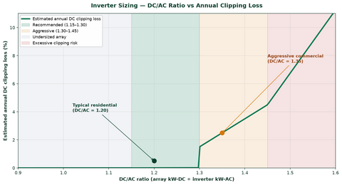
A DC/AC ratio between 1.20 and 1.35 is the sweet spot for most installations — more energy in the morning, evening, and cloudy hours, with clipping losses held under 3%. Climate pulls that number around. In hot markets like Arizona or Nevada, where cell temperatures regularly exceed 65°C, thermal derating already eats DC output, so hold the ratio to 1.10–1.20. In cool, cloudy climates like the Pacific Northwest — our home turf — pushing to 1.30–1.40 makes economic sense because the inverter rarely sees full AC output. We design Portland-area systems at 1.25–1.35 as a default and almost never see clipping losses worth worrying about.
String Voltage Calculations
String voltage sizing is where most design errors occur. Every inverter has three voltage parameters you must respect: maximum input voltage, MPPT voltage range (minimum and maximum), and startup voltage. Your string configuration must keep operating voltages inside those bounds across all temperature conditions.
Step 1: Determine maximum string voltage
The maximum number of panels in series is limited by the inverter's maximum input voltage and the lowest expected operating temperature. Panel voltage rises as temperature drops, so apply the voltage temperature coefficient at the site's record low:
V_max_string = N_panels × V_oc × (1 + (T_low − T_STC) × TC_Voc)
Where:
- N_panels = number of panels in series
- V_oc = open-circuit voltage at STC (from the panel datasheet)
- T_low = record-low temperature for the site (°C)
- T_STC = 25°C (standard test condition)
- TC_Voc = temperature coefficient of Voc (typically −0.30%/°C, expressed as −0.003/°C)
Worked example: a panel with V_oc = 49.8 V at STC and TC_Voc = −0.30%/°C, installed where the record low is −15°C. The correction factor is 1 + (−15 − 25) × (−0.003) = 1 + 0.12 = 1.12. Corrected V_oc per panel = 49.8 × 1.12 = 55.8 V. On an inverter with a 1,000 V max input, maximum panels in series = floor(1000 / 55.8) = 17 panels. I've seen this exact calculation skipped on a Minnesota job — 18 panels on a string that maxed at 17, one polar vortex, one dead inverter, one warranty claim denied. Run the number.
Step 2: Verify minimum MPPT voltage
The string must also hold enough voltage to stay inside the MPPT operating range at high temperature. Panel voltage falls as temperature rises, so check the minimum at the highest expected cell temperature (typically 70°C for roof-mounted panels):
V_mp_hot = N_panels × V_mp × (1 + (T_high − T_STC) × TC_Vmp)
Where V_mp is maximum-power voltage at STC and TC_Vmp is its temperature coefficient (typically −0.35%/°C). The result must exceed the inverter's minimum MPPT voltage — typically 150–330 V for residential string inverters and 500–850 V for commercial models.
Step 3: Calculate string current
Each MPPT input carries a maximum input current. For series-connected panels, string current equals the panel's short-circuit current (Isc) times the NEC 690.8 safety factors. Per NEC 690.8(A)(1), maximum PV circuit current is 1.25 × Isc; per NEC 690.8(B), conductors and overcurrent devices size at 1.25 × that value — a combined 1.56 factor:
I_circuit = Isc × 1.56
This figure must not exceed the MPPT's maximum input current or the conductor ampacity after all derating. Conductor selection for those homeruns lives in our MC4 solar wire gauge guide and the PV wire vs. USE-2 vs. THHN guide.
NEC Article 690 Requirements for Inverter Sizing
NEC Article 690 governs PV installations and directly shapes inverter sizing. Passing inspection and sleeping at night both require knowing these sections.
NEC 690.7: Voltage and current ratings
NEC 690.7(A) requires PV system voltages to be based on the lowest expected ambient temperature, and the code publishes correction factors for crystalline silicon modules:
| Lowest Ambient Temp (°C) | Correction Factor |
|---|---|
| 24 to 10 | 1.02 |
| 9 to 0 | 1.04 |
| -1 to -10 | 1.06 |
| -11 to -20 | 1.08 |
| -21 to -40 | 1.10 |
At −10°C the factor is 1.14, so a panel rated 45 V_oc produces 51.3 V under those conditions — and the inverter plus all DC-side equipment must be rated for it. For modern modules, the manufacturer-calculated coefficient may differ slightly from the NEC table; the code permits using the manufacturer's coefficient when it's more accurate.
NEC 690.8: Circuit sizing and current
NEC 690.8(A)(1) establishes maximum PV circuit current at 156% of Isc, covering irradiance above STC (1,000 W/m²) under edge-of-cloud and high-altitude conditions. NEC 690.8(B)(1) then requires overcurrent devices and conductors rated at no less than 125% of that maximum current — the combined 1.56 multiplier.
NEC 690.9: Overcurrent protection
String fuses must be rated at no less than 156% of Isc and must not exceed the panel's maximum series fuse rating on the datasheet. Paralleled strings each need overcurrent protection unless the inverter's integrated string fuses satisfy the requirement.
NEC 690.10: Stand-alone systems
For off-grid and hybrid systems, NEC 690.10 requires the inverter output to supply the maximum connected load, or an energy storage system capable of covering the deficit — directly relevant when sizing hybrids for backup. Our hybrid inverter guide covers that sizing path.
MPPT Configuration and Stringing Strategy
Maximum Power Point Tracking is the algorithm that extracts maximum power from the DC array. Modern string inverters carry dual or quad MPPT inputs, allowing independent tracking of different orientations, tilts, or panel counts. Distributing strings across MPPTs correctly is worth real kilowatt-hours.
Single vs. dual vs. quad MPPT
| MPPT Configuration | Best Use Case | Key Advantage |
|---|---|---|
| Single MPPT | Uniform roof, single orientation | Lower cost, simpler design |
| Dual MPPT | Two roof planes (e.g., east/west) | Independent tracking per orientation |
| Quad MPPT | Complex roofs, multiple orientations, shading | Maximum design flexibility |
Stringing rules for multi-MPPT inverters
- Same orientation on one MPPT: panels sharing an MPPT input should share azimuth and tilt for optimal tracking.
- Equal string lengths: paralleled strings on the same MPPT need identical panel counts. Mismatched strings force the tracker to a suboptimal averaged power point.
- Shading isolation: shaded strings go on their own MPPT so they don't drag the unshaded strings down.
- Current limits: combined Isc of paralleled strings must not exceed the MPPT's maximum short-circuit input rating.
Oversizing Guidelines: When and How Much
DC oversizing (a DC/AC ratio above 1.0) is a deliberate strategy that trades a little peak clipping for more annual energy. The economics work because inverters run most efficiently at 50–80% of rated load, and real-world conditions rarely produce STC output.
Benefits of oversizing
- Higher annual yield: the inverter reaches rated output earlier and holds it later, increasing daily production.
- Better low-light performance: more DC capacity crosses the startup threshold sooner at dawn and holds it later at dusk.
- Lower cost per watt: a smaller inverter for a given array cuts inverter cost, BOS, and AC-side wiring.
- Less clipping than theory predicts: degradation, soiling, and thermal losses mean actual DC output rarely touches nameplate.
When oversizing becomes detrimental
- Above a 1.50 DC/AC ratio: clipping losses start outweighing the gains, and warranty terms may be affected.
- Exceeding maximum DC input: every inverter has a hard DC power input limit (typically 1.5–2.0× AC rating). Never cross it.
- High-irradiance climates: in Phoenix or Las Vegas, clipping at a 1.3 ratio can exceed 5%, eroding the case for aggressive oversizing.
- Warranty constraints: some manufacturers void coverage above a stated DC/AC maximum, commonly 1.50 or 1.55.
If clipping is already eating production on an existing system, our guide to solar inverter clipping causes and fixes walks the mitigation options.
Practical Sizing Example
A complete residential calculation, start to finish.
System parameters
- Panel: 450 W, V_oc = 49.8 V, V_mp = 41.5 V, Isc = 11.6 A
- Inverter: 10 kW, dual MPPT, max input voltage 1,000 V, MPPT range 150–800 V, max input current 26 A per MPPT
- Site: Portland, OR, record-low −7°C, design high cell temp 70°C
- Array: 24 panels on the south roof, 4 on an east porch (28 total = 12.6 kW DC)
Maximum panels per string
Voltage correction at −7°C: 1 + (−7 − 25) × (−0.003) = 1 + 0.096 = 1.096. Corrected V_oc = 49.8 × 1.096 = 54.6 V. Max panels = floor(1000 / 54.6) = 18 panels.
Minimum panels per string
V_mp at 70°C: 41.5 × (1 + (70 − 25) × (−0.0035)) = 41.5 × 0.8425 = 35.0 V. Minimum panels for the 150 V MPPT floor: ceil(150 / 35.0) = 5 panels.
String configuration
South roof (24 panels): two strings of 12 on MPPT 1. Each string's V_mp_hot = 12 × 35.0 = 420 V (inside 150–800 V), V_oc_cold = 12 × 54.6 = 655 V (under the 1,000 V limit).
East porch (4 panels): cannot form a viable string alone — below the MPPT minimum. These panels need microinverters, optimizers, or consolidation into the south array if wiring allows. Our microinverter collection exists for exactly this problem.
Current check
String current = Isc × 1.56 = 11.6 × 1.56 = 18.1 A. Two paralleled strings = 36.2 A, exceeding the 26 A MPPT limit. Solution: put each 12-panel string on its own MPPT, or select an inverter with higher input current.
DC/AC ratio check
12,600 W DC / 10,000 W AC = 1.26 — inside the recommended 1.20–1.35 band, with expected annual clipping loss under 1% for the Portland climate.
Worked configuration summary
| Parameter | String A (South) | String B (South) | Limit | Pass? |
|---|---|---|---|---|
| Panels in series | 12 | 12 | 5–18 allowed | Yes |
| V_oc at record low (−7°C) | 655 V | 655 V | < 1,000 V | Yes |
| V_mp at 70°C cell temp | 420 V | 420 V | > 150 V MPPT min | Yes |
| Circuit current (Isc × 1.56) | 18.1 A | 18.1 A | < 26 A per MPPT | Yes (separate MPPTs) |
| Array DC / inverter AC | 12.6 kW / 10 kW = 1.26 | 1.20–1.35 target | Yes | |
Typical String Lengths by Inverter Class
Use these as a sanity check against your own math — they assume modern 450 W-class residential panels with ~50 V V_oc and the temperature corrections above:
| Inverter class | Max DC input voltage | Typical MPPT range | Typical string length (panels) | Notes |
|---|---|---|---|---|
| Residential, 600 V class | 600 V | ~90–550 V | 6–10 | Common on older/small residential units |
| Residential, 1,000 V class | 1,000 V | ~150–800 V | 5–17 | Modern standard; verify cold-weather Voc |
| Commercial, 1,100 V class | 1,100 V | ~200–950 V | 7–19 | Three-phase rooftop systems |
| Commercial, 1,500 V class | 1,500 V | ~500–1,300 V | 12–26 | Ground-mount and large commercial |
Common Sizing Mistakes to Avoid
- Ignoring temperature coefficients: skipping the cold-temperature voltage rise is the leading cause of inverter damage and denied warranties.
- Mismatched strings on a shared MPPT: parallel strings with different panel counts force an averaged power point, costing 5–15% of yield.
- Overcrowding a single MPPT: exceeding the input current limit makes the inverter curtail input — paid-for DC capacity that never becomes AC.
- Neglecting voltage drop: long DC homeruns can push string voltage below the MPPT minimum under load. Size conductors to hold drop under 2%; our NEC ampacity guide covers the conductor math.
- Disregarding efficiency curves: inverters peak at 30–70% of rated load. A grossly oversized unit loafing at 10% converts poorly all day.
Selecting the Right Inverter for Your Array
Prioritize these specifications, in this order:
- Maximum DC input voltage: must exceed your cold-temperature string voltage with margin.
- MPPT voltage range: wide enough to cover your minimum and maximum operating voltages.
- Number of MPPT inputs: match the count of distinct orientations or shading zones.
- Maximum input current per MPPT: must carry your combined string current after NEC derating.
- Maximum DC power input: confirm it supports your target DC/AC ratio.
- Certifications: UL 1741 listing is required for US grid connection; UL 1741 SB covers the advanced grid-support functions IEEE 1547-2018 demands in most jurisdictions.
Explore our complete inventory of grid-tie and hybrid string inverters from leading manufacturers. Need charge controllers for an off-grid or battery-based build? Browse the charge controller selection and our charge controller sizing guide. Surge protection for the DC and AC sides is covered in our SPD sizing and installation guide. All orders ship within 7–10 business days.
The Bottom Line on String Sizing
The designs that pass inspection and produce for 25 years all share one trait: somebody ran the voltage math at both temperature extremes before ordering hardware. Work the DC/AC ratio for your climate, verify cold Voc and hot Vmp against the MPPT window, respect the 1.56× current factor, and distribute strings across MPPTs by orientation. Do those four things and the inverter choice narrows itself to two or three models — at that point, buy on warranty and monitoring.
Shop This Article
Ready to specify equipment? PES Supply stocks 50,000+ SKUs from 169 authorized brands with delivery in 7–10 business days. Top picks based on the topics above:
- SMA Sunny Boy 5.0-US Inverter — 97% efficiency, residential grid-tied
- SMA Sunny Boy 3.8-US Inverter — 97% efficiency, small residential
- Fronius Symo ADVANCED 15.0-3 480VAC — 15kW three-phase, commercial
- Sol-Ark 12K Hybrid Inverter — 12kW, battery-based, off-grid/hybrid
Browse the complete selection: Inverters | Solar Panels | Microinverters
Frequently Asked Questions
What is the optimal DC/AC ratio for a solar system?
The optimal DC/AC ratio is typically 1.1–1.3, balancing clipping losses against inverter cost. A ratio of 1.2 is common for residential systems. Higher ratios of 1.3–1.4 work in cloudy climates where peak production is rare; high-irradiance Southwest sites should stay at 1.1–1.2.
What happens if I undersize my inverter?
Undersizing causes clipping, where the inverter cannot convert all available DC power during peak production — typically a 2–6% annual energy loss. Some array oversizing relative to the inverter is intentional and economical; excessive undersizing wastes energy.
How do I calculate string voltage for cold weather?
Multiply the panel's open-circuit voltage by a correction factor derived from its temperature coefficient at your site's record low: V_oc × (1 + (T_low − 25) × TC_Voc). The corrected string voltage must stay below the inverter's maximum input rating. NEC 690.7 requires using the record low, and publishes its own correction-factor table.
How many panels can I put on one MPPT?
It depends on the inverter's voltage window and current limit, the panel's Voc and Vmp at temperature extremes, and whether strings parallel. Calculate minimum string length from the MPPT voltage floor at high cell temperature, maximum from cold-weather Voc against the input voltage ceiling, then verify combined current stays under the MPPT's input rating.
Does NEC Article 690 affect inverter sizing?
Yes. NEC 690.7 sets voltage ratings from record-low temperatures, 690.8 defines the 1.56× Isc circuit-sizing factor, 690.9 governs overcurrent protection, and 690.10 covers stand-alone system output requirements. The inverter's ratings anchor conductor and breaker sizing on both sides of the system.
Related Articles
- Hybrid Inverter Guide: How They Work, Sizing & Best Models (2026) — linked in the NEC 690.10 section above
- Hybrid Inverter vs. Off-Grid Inverter: Choosing the Right System
- Solar Inverter Clipping: Causes, Impact, and How to Avoid It
Ready to Source Your Equipment?
Browse 50,000+ SKUs from 169 authorized brands. Trade pricing with full OEM warranties.
Shop All Categories Request a Quote