Solar Inverter Clipping: Causes, Impact, and How to Avoid It
By the PES Supply Editorial Team
Inverter clipping happens when your solar array can produce more DC power than your inverter can convert to AC — the production curve flattens at the inverter's nameplate and the surplus is discarded. It sounds like a defect. It is actually one of the most deliberate, well-understood design trade-offs in photovoltaics, and getting the DC/AC ratio right is worth thousands of kilowatt-hours over a system's life.
This guide covers what clipping is, how much energy it really costs by climate and ratio, how each inverter architecture behaves, and the six design levers that keep clipping where it belongs — small, predictable, and paid for many times over by the oversized array. Shopping the hardware? Start with our solar inverter catalog and inverter sizing calculator.
Every grid-tied inverter has a maximum AC output rating — the number on the nameplate, say 7.6 kW. The solar array behind it, measured in DC watts under standard test conditions, is usually bigger: 9, 10, sometimes 13 kW of DC. When the array can produce more DC power than the inverter can convert to AC, the inverter holds its output flat at the nameplate ceiling and discards the surplus. That flat-topped section of the production curve is clipping.
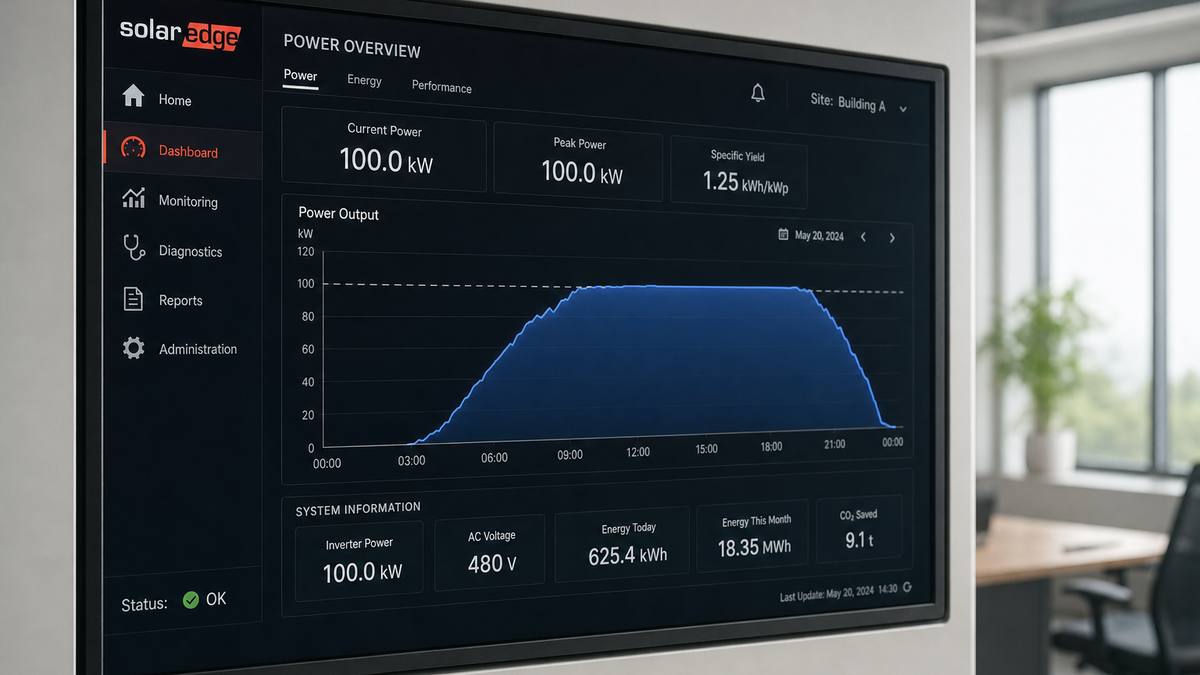
Picture a sunny April day, cool panels, clean glass: the array ramps hard toward noon and wants to deliver 10.5 kW, but the 7.6 kW inverter pins the output at 7.6 kW from 11:00 to 13:30. The energy in the flattened triangle above the line — energy the panels were physically capable of delivering — never becomes AC. It simply stays in the array as untaken potential.
Clipping is not a fault, a warranty issue, or a sign of a broken system. It is a deliberate design decision. The entire economics question is whether the energy thrown away at peak is worth less than the extra energy harvested in the mornings, evenings, winters, and cloudy hours that a larger DC array captures. Usually — emphatically — it is.
Key Takeaways
- Clipping = array DC power exceeds inverter AC ceiling; the surplus is discarded at peak hours only.
- The industry-standard DC/AC ratio sweet spot is 1.20–1.35 for residential string systems; up to 1.45 for hybrid systems with batteries that absorb the peak.
- Annual clipping losses at a 1.25 ratio are typically under 1–2% of yearly production, while the oversized array adds 15–25% more annual energy.
- Clipping concentrates in cool, bright spring months — not hot summer afternoons, because heat depresses panel output.
- Batteries, east-west orientations, and export-limit controls all convert "clipped" energy into used energy.
Solar panels rarely see their nameplate conditions. STC assumes 1,000 W/m² irradiance and a 25 °C cell temperature. Real roofs deliver that combination for a few dozen hours a year — cool, clear, perpendicular sun. The rest of the time the array produces 40–85% of nameplate. An inverter sized exactly to the array's DC rating spends almost its entire life running at partial load, where conversion efficiency is slightly worse and the customer paid for AC capacity that never gets used.
Oversizing the DC array relative to the inverter — the DC/AC ratio — fixes both problems at once. The inverter reaches its efficient operating zone earlier in the morning and stays there later into the evening. Shoulder-season production climbs. Cloudy-day output climbs. The only hours sacrificed are the peak-production hours that were going to be curtailed anyway, and those hours are the cheapest energy the system makes, because the marginal cost of extra panels keeps falling while inverters, permitting, and labor stay expensive per added kilowatt.
We have reviewed monitoring data from enough systems to say this plainly: a 1.0 ratio system and a 1.3 ratio system on the same roof differ by 20%+ in annual kWh, and the clipping penalty on the 1.3 system is usually under 2% annually. The trade is not close.
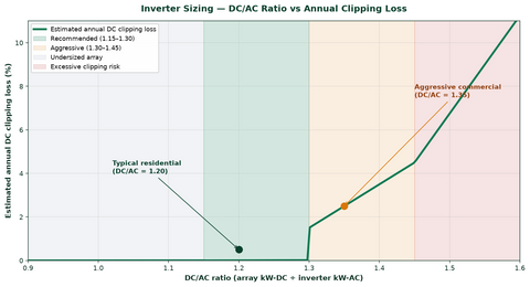
Clipping loss is a function of the DC/AC ratio and the local solar resource. The table below models typical annual clipping losses — the percentage of total potential annual production discarded at the inverter ceiling — across three climate archetypes (PSH = average peak sun hours per day):
| DC/AC Ratio | Mild Climate (PNW, 4.5 PSH) | Moderate Climate (Northeast, 4.8 PSH) | Hot, High-Resource Climate (SW, 6.5 PSH) |
|---|---|---|---|
| 1.00 | 0% | 0% | 0% |
| 1.10 | 0% | 0% | < 0.5% |
| 1.20 | < 0.5% | 0.5% | 1–2% |
| 1.30 | 0.5–1% | 1–2% | 3–5% |
| 1.40 | 1–2% | 2–4% | 5–8% |
| 1.50 | 2–4% | 4–6% | 8–12% |
Two reads on that table. First, even at a 1.30 ratio in a strong solar resource, annual losses stay in single digits — and the 30% larger array is harvesting far more than that in the shoulders. Second, hot climates clip more than cool ones at the same ratio, which confuses people until you remember that clipping is driven by irradiance-hours, not temperature: the Southwest simply has more hours above the clipping threshold, even though each hot panel is individually less efficient. The worst single clipping days everywhere are bright, cold spring days, when cool cells run efficiently at high irradiance.
Worked example: a 10 kW DC array on a 7.6 kW inverter (1.32 ratio) in a moderate climate might clip 1.5% of potential annual production — about 210 kWh on a system making ~14,000 kWh/yr. Meanwhile the same roof at a 1.0 ratio (7.6 kW DC) would make roughly 11,600 kWh/yr. The "wasteful" oversized system nets 2,200+ more kWh per year after clipping. At $0.15/kWh that is $330 a year, every year, for a couple extra panels' worth of upfront cost.
| System Type | Typical DC/AC Ratio | Clipping Risk | Mitigation Strategy |
|---|---|---|---|
| String inverter (residential) | 1.20–1.35 | Moderate | Optimize ratio for climate |
| String inverter (commercial) | 1.25–1.40 | Moderate to high | East-west orientation, battery storage |
| Microinverter system | 1.00–1.10 | Very low | Inherent to design |
| Power optimizer system | 1.15–1.30 | Low | Per-panel MPPT reduces mismatch |
| Hybrid with battery | 1.25–1.45 | Low (battery absorbs excess) | Charge during peak production |
| Tracker systems | 1.30–1.45 | High | Conservative ratio, larger inverter |
Microinverters clip per-panel — a 430 W panel on an IQ8-class microinverter rated 384 VA will flat-top that panel at its own ceiling. The penalty is small but real, and it is why pairing today's 440–470 W modules with older, lower-rated microinverters is a mismatch we actively steer customers away from; check our microinverter selection against panel nameplate before finalizing a BOM. Hybrid inverters change the math most dramatically: clipped DC is not lost if it can charge a battery, so hybrid systems justify the highest DC/AC ratios in the table. Our inverter buyer's guide walks the full selection tree.
- Ratio drift from module upgrades. Repowering a 2016-era array with modern 440 W panels on the original inverter quietly pushes a 1.15 ratio to 1.35+. Sometimes that is fine; sometimes it doubles clipping losses. Re-run the numbers before swapping panels.
- Bifacial gain nobody modeled. A bifacial array over white membrane or bright gravel can add 6–15% rear-side gain — all of which lands exactly at peak sun, right on top of the clipping window. Model bifacial systems with the gain included, not as a bonus.
- Cold-snap production spikes. A bright 5 °F morning can push an array 10% above STC nameplate. Systems designed to "never clip" in July still clip in February.
- Utility export limits. Some interconnection agreements cap AC export below the inverter's rating — a 7.6 kW inverter export-limited to 5 kW clips against the lower ceiling whenever the house is not consuming the difference. Self-consumption and batteries recover most of it.
- Soiling recovery. The day after a cleaning (or a hard rain after a dusty month) is often the highest-clipping day of the season — the array suddenly delivers production the inverter had stopped expecting.
From our side of the counter: the most common clipping complaint we field is not "my system clips" — it is "my production graph has a flat top, is something broken?" Ninety percent of the time the answer is the system is working exactly as designed, and the flat top is the ratio doing its job.
A healthy DC/AC ratio only works if the strings actually fit the inverter's MPPT windows. Every string design has to satisfy four constraints at once — cold-weather Voc below the input maximum, hot-weather Vmp above the MPPT minimum, string current below the input limit, and total array watts at your target ratio. Miss any one and the "clipping" you see is actually a design error.
| Design Constraint | Rule | Worked Check (430 W module, Voc 49.1 V, Vmp 41.2 V, Imp 10.4 A) |
|---|---|---|
| Cold-weather Voc | Voc(cold) = Voc × [1 + |βVoc| × (25 − Tmin)] must stay under the inverter's 600 V (residential) input max | 10 modules: 49.1 × 1.14 (−10 °F design temp, β ≈ −0.25%/°C) ≈ 560 V ✓ under 600 V |
| Hot-weather Vmp | Vmp(hot) must stay above the MPPT floor | 10 modules: 41.2 × 0.82 (65 °C cell) ≈ 338 V ✓ above a 200 V MPPT floor |
| Input current | String Imp under the MPPT's rated current | 10.4 A ✓ under a 12.5 A input |
| Ratio target | Total DC ÷ inverter AC = 1.20–1.35 | Two strings of 10 × 430 W = 8.6 kW DC on a 7.6 kW inverter = 1.13 → add a third string where roof allows: 12.9 kW DC = 1.70 ✗ too far; reconfigure to 11.4 kW = 1.50 on hybrid with battery ✓ |
Conductor sizing for those strings follows NEC 690.8: circuit current at 125% of Isc, then another 125% for continuous duty — 156% of Isc total, so a string with 13.7 A Isc lands on 15 A conductors and a 15 A breaker. Twelve AWG PV wire handles it with margin on most residential runs; the full ampacity tables live in our NEC wire ampacity chart.
| String Isc | NEC 690.8 Design Current (×1.56) | Min. Copper Conductor (90 °C PV Wire) | Overcurrent Device (NEC 240.6) |
|---|---|---|---|
| 13.7 A (typical residential string) | 21.4 A | 12 AWG (30 A) | 15–20 A where required |
| 17.2 A (high-current 210 mm modules) | 26.8 A | 10 AWG (40 A) | 30 A where required |
| 27.4 A (two paralleled strings) | 42.7 A | 8 AWG (55 A) | 50 A |
1. Set the ratio for the climate, not the brochure
Use the loss table above: 1.20–1.30 in high-resource climates, 1.25–1.35 in mild and moderate ones. Going past 1.40 without storage starts throwing away real money in the Southwest.
2. Add a battery before you add a bigger inverter
A hybrid inverter charging a battery through the peak converts clipped energy into stored energy. Oversizing to 1.35–1.45 with a battery usually beats a larger central inverter on both cost and resilience. See our battery bank sizing guide.
3. Split orientations east-west
Splitting the array across two roof faces flattens and widens the production curve — more morning and evening energy, a lower noon peak, and less time at the inverter ceiling, all at the same DC/AC ratio.
4. Match MLPE ratings to modern modules
With microinverters or optimizers, verify the per-unit AC rating against the panel's realistic peak output, not just its STC watts. A 470 W panel on a 350 VA micro will flat-top every good day.
5. Use export limiting intelligently
Where the utility caps export, set the inverter's export limit and let the balance serve the house or charge storage — the system only "clips" against the export ceiling, not its own hardware ceiling.
6. Model it before you build it
Any serious design tool models hourly clipping from a TMY weather file. If a quote shows a 1.4 ratio with zero clipping losses modeled, the production estimate is optimistic — ask for the 8760.
For the electrical side of the build — string sizing, conductor ampacity, and the NEC 690 requirements that govern the DC side — our solar wire and cable guide, NEC 690 disconnect guide, and NEC compliance guide carry the tables.
You do not need modeling software to spot clipping — your monitoring app shows it. A clipped day has a production curve with a visibly flat plateau at the inverter's nameplate, usually between late morning and early afternoon, on otherwise cloudless days. Compare against a cloudy day: a soft, rounded curve means the inverter never hit its ceiling.
Three diagnostics we run when a customer sends us a flat-topped graph:
- Plateau exactly at AC nameplate? Normal clipping at a healthy ratio. Confirm it only happens on the best production days.
- Plateau below nameplate? Something else is wrong — export limit, thermal derating (inverters derate above ~45–50 °C internal temperature; check ventilation and direct sun on the unit), or a tripped string.
- Flat top that appeared suddenly? After a panel upgrade, a cleaning, or a season change, that is expected. After nothing changed, look for a new export cap or a failing MPPT input.
Thermal derating deserves its own sentence because it masquerades as clipping: an inverter mounted in a hot garage or full western sun will pull its own ceiling down on the very days the array is strongest. We have "fixed" more than one clipping complaint by moving nothing and adding a shade plate over the inverter.
Is inverter clipping bad for the equipment?
No. Clipping is a normal operating mode — the inverter limits its output to its rated capacity, which is precisely what it is designed to do. It does not stress the inverter, panels, or wiring. The only cost is the unharvested energy at peak hours.
What DC/AC ratio should I design for?
For residential string systems, 1.20–1.35 is the industry sweet spot: up to 1.30 in high-irradiance climates, up to 1.35 in mild ones. Hybrid systems with batteries can justify 1.35–1.45 because the battery absorbs peak surplus instead of the inverter discarding it.
How much energy does clipping actually cost per year?
At a 1.25–1.30 DC/AC ratio, typical annual clipping losses are 1–2% in moderate climates and 3–5% in high-resource hot climates — far less than the 15–25% annual energy gain from the oversized array. On a 14,000 kWh/yr system, a 1.5% clipping loss is about 210 kWh, roughly $30–$35 at typical residential rates.
Why does my system clip more in spring than summer?
Clipping peaks when irradiance is high and cells are cool — cool silicon converts more efficiently. Bright, cold spring days produce the highest instantaneous DC power of the year. Summer afternoons have strong sun but hot cells running 10–15% below their cool-weather output, so the array rarely reaches the inverter ceiling.
Can a battery eliminate clipping losses?
Mostly, yes. A hybrid inverter can route DC power above the AC ceiling into a battery rather than discarding it. The energy is not lost — it is time-shifted to evening use. This is why storage-paired systems tolerate higher DC/AC ratios than grid-only systems.
My monitoring shows a flat top below the inverter's rating. Is that clipping?
Probably not. A plateau below nameplate usually indicates an export limit, thermal derating from a hot installation location, or a hardware issue. True clipping flat-tops exactly at the inverter's AC nameplate on the sunniest days. Check the installation environment and any utility export cap first.
- IEC 61724 — Photovoltaic system performance monitoring and measurement
- NEC 690 / 705 — PV system requirements and interconnected power sources
- NREL research on DC/AC ratio optimization and inverter loading
- Manufacturer inverter datasheets — AC nameplate ratings, thermal derating curves, MPPT windows
Shop Inverters at PES Supply
Contractor pricing on string, hybrid, and micro inverters — ships from 12+ US hubs.
Browse solar inverters →Keep designing: top solar inverter picks for 2025, the inverter buyer's guide, hybrid solar inverter explained, and the system size calculator. Shop string inverters, hybrid inverters, microinverters, and battery storage. Pairing storage? See the battery sizing guide and charge controller sizing guide.
PES Supply (https://www.portlandiaelectric.supply) is a B2B electrical and solar distributor offering 50,000+ SKUs from 169 authorized brands. Verify all specifications against the manufacturer's current datasheet before final design.