Updated September 2026 — content reviewed and refreshed by the PES team. For current pricing and availability, see the linked product pages or request a quote.
Solar Wire and Cable Guide: PV Wire vs USE-2 vs THHN — Sizing, Selection, and NEC Compliance
Wire types, ampacity derating, voltage drop, conduit fill, MC4 connectors, and grounding — the complete field reference for solar PV wiring per NEC 690.
We've pulled thousands of feet of 10 AWG PV wire across commercial rooftops in August, and the wire you spec decides whether that array still passes inspection — and still produces — twenty summers from now. Pick the wrong insulation for an exposed run and the jacket chalks, cracks, and fails a megger test inside of five years. Undersize a home run and you bleed 3% of your production to voltage drop every single day the sun shines.
This guide is the reference our counter staff uses when a contractor calls in with a string layout and a question. It covers the three wire types that actually belong in a PV system, the NEC 690 rules that govern where each one can go, and the four calculations — ampacity, temperature derating, voltage drop, and conduit fill — that turn a wiring plan into a code-compliant bill of material.
Every table below carries real numbers you can spec from: NEC 310.16 ampacities, 250.122 grounding sizes, actual resistance values per 1,000 feet. Bookmark it. We keep a printed copy at the will-call desk.
Four conductor types cover roughly 99% of what goes into a code-compliant PV install. They are not interchangeable, and the differences are not marketing — they're listing standards, temperature ratings, and where the inspector will let you put them.
1.1 PV Wire (UL 4703)
PV wire is the purpose-built conductor for photovoltaic arrays, listed to UL 4703. It's sunlight resistant as a condition of the listing — not optional, not "marked on request" — rated 90°C wet and dry, and available in 600 V, 1,000 V, and 2,000 V ratings to match modern string voltages. The insulation is a thick cross-linked polyethylene (XLPE) jacket over fine-stranded tinned copper, typically 19 strands on the common 12–10 AWG sizes, which is why it flexes around module frames without fighting you.
PV wire is the only single-conductor cable NEC 690.31(C)(1) blesses for exposed, non-raceway array wiring when it's used with listed PV cable clips and ties. If the run is in free air between modules, hanging off the racking, this is your wire. We stock it in 2,500-foot 2,000 V master reels for commercial jobs. You can browse the full lineup in our PV wire collection.
One field note most spec sheets skip: buy the 2,000 V rated spool even on 1,000 V systems. The price difference is pennies a foot, and the thicker jacket survives zip-tie over-tensioning and sharp racking edges noticeably better. I stopped speccing 600 V PV wire on rooftops after watching a jacket fail at a clamp edge on a three-year-old array.
1.2 USE-2 (Underground Service Entrance)
USE-2 is the legacy solar workhorse — a 600 V, 90°C wet/dry, sunlight-resistant single conductor listed to UL 44/UL 854. It was the default array wire before PV wire existed, and it's still code-legal for exposed array wiring when it carries the RHW-2 marking (the dual listing is printed as "USE-2/RHW-2" on the jacket). You'll find it on half the arrays built between 2008 and 2016, and it remains the right choice for direct-burial runs from a ground mount to the inverter pad — that "U" in USE means it's listed to sit in dirt.
Where USE-2 loses to PV wire: voltage rating (600 V caps it out of high-voltage string designs) and stranding. USE-2 is usually coarser-stranded, so it's stiffer to dress behind modules. For a ground mount with a buried home run, we sell a pre-cut USE-2/PV wire harness with the #6 bare copper EGC already paired, which saves a pull on two-string residential ground mounts.
1.3 RHW-2
RHW-2 is a 90°C wet-rated, flame-retardant conductor. On its own it lacks the sunlight-resistance requirement for exposed array use — but as noted above, virtually all USE-2 sold for solar carries the dual USE-2/RHW-2 marking, and that combination is explicitly permitted by 690.31(C)(1). If you're holding a spool marked only "RHW-2" with no USE-2 and no sunlight-resistant marking, it does not go on the roof in free air. Raceway only.
1.4 THHN / THWN-2
THHN is the most common building wire in North America, and it absolutely has a place in PV systems — inside raceways, not in free air. The dual-rated THHN/THWN-2 jacket (which is what everyone actually stocks; straight THHN-only is rare now) is rated 90°C wet and dry, costs roughly half of PV wire per foot, and pulls beautifully through EMT. Use it from the rooftop junction box down, for inverter AC output circuits, and for any DC run that lands inside a building — 690.31(E) requires DC conductors inside a building to live in a metal raceway anyway, and THWN-2 in EMT is how that gets done at a sane price.
What THHN/THWN-2 cannot do: hang exposed on a racking rail. No standard sunlight-resistant listing, no 690.31(C) permission. If your design has exposed conductors on the array, that's PV wire territory, full stop. For the raceway portions, we stock Cerro 8 AWG THHN/THWN-2 in 500-foot spools and the full gauge run in our THHN wire collection and broader wire and cable aisle.
1.5 Wire Type Comparison Table
| Property | PV Wire | USE-2 / RHW-2 | THHN | THWN-2 |
|---|---|---|---|---|
| UL Standard | UL 4703 | UL 44 / UL 854 | UL 83 | UL 83 |
| Max Temperature | 90–125°C | 90°C | 90°C (dry) | 90°C (wet/dry) |
| Voltage Rating | 600/1000/2000 V | 600 V | 600 V | 600 V |
| Sunlight Resistant | Yes (standard) | Yes (must be marked) | No (unless marked) | No (unless marked) |
| Direct Burial | Yes (if listed) | Yes | No | No |
| Flame Resistant | Yes | No | Yes (nylon jacket) | Yes (nylon jacket) |
| Exposed DC Array Wiring | Yes | Yes (with RHW-2 marking) | No | No |
| Inside Buildings (in raceway) | Yes | No (limited) | Yes | Yes |
| AC Wiring (in conduit) | Yes | Yes | Yes (dry only) | Yes |
| Typical Use in PV | DC array & home runs | DC array & direct burial | AC raceway runs | AC/DC raceway runs |
PV wire's fine stranding is a listing requirement, not a nicety. UL 4703 sets minimum strand counts so the conductor survives the flexing of thermal cycling on a racking rail:
| PV Wire AWG | Minimum Number of Strands |
|---|---|
| 18 AWG | 17 |
| 16–10 AWG | 19 |
| 8–4 AWG | 49 |
| 2 AWG | 130 |
| 1 AWG–1000 kcmil | Per manufacturer listing |
Article 690.31 tells you which wiring methods are permitted for PV source and output circuits. Read it before you pull a single foot, because the answer changes depending on where the conductor sits.
2.1 Permitted Wiring Methods (690.31(A))
PV source and output circuits may use any Chapter 3 wiring method — EMT, PVC, RMC, FMC where allowed, cable trays, and listed single-conductor cables. The practical translation: conduit is always legal everywhere; exposed cable is legal only where a specific subsection says so.
2.2 Single-Conductor Cables (690.31(C))
690.31(C)(1) is the clause that makes modern array wiring possible: single-conductor, sunlight-resistant cable — Type PV wire, and USE-2/RHW-2 — is permitted exposed (not in raceway) for PV array wiring within the array boundary. The conditions that inspectors actually enforce:
- Cable must be secured with listed PV wire clips or UV-rated ties at intervals that keep it off the roof surface and off sharp edges.
- It follows the racking; it does not festoon between rows.
- Once the circuit leaves the array — heading down to an inverter, combiner, or junction box — many AHJs want it in a raceway at the transition, and 690.31(G) and local amendments often require it. Plan a junction box at the array edge and switch to conduit there.
2.3 Wiring Inside Buildings (690.31(E))
DC PV circuits inside a building must be in a metal raceway (EMT, RMC, IMC, flexible metal conduit) or Type MC metal-clad cable, from the point of penetration to the first readily accessible disconnect. The logic is firefighter safety: energized DC from a sunlit array stays live during a fire, and steel conduit keeps an axe or a burnt-through wall from energizing the structure. PVC does not qualify here. Neither does Romex, ever, on the DC side.
Marking matters too — 690.31(E)(3) and 690.56 require "WARNING: PHOTOVOLTAIC POWER SOURCE" labels on raceways, enclosures, and pull boxes at 10-foot intervals and at every penetration. A failed label kit has failed more final inspections on our jobs than any wiring defect. Buy the red reflective labels in bulk and put a roll in every truck.
Conductor ampacity is not a fixed number. NEC 310.16 gives ampacities at a 30°C ambient; a rooftop in Phoenix at 2 p.m. is not 30°C. The wire on a dark shingle roof under a glass module runs far hotter than the air temperature the weather app reports, and the correction factors eat ampacity you thought you had.
3.1 Rooftop Temperature Adder
For conductors in raceways or cables on or above a rooftop in sunlight, NEC 310.15(B)(3)(c) historically added 33°F (about 17°C) to the ambient for low clearances — and while the 2020/2023 code moved the adder into Table 310.15(B)(3)(c) based on clearance height (7/8 inch to 3.5 inches = add 40°F to the design ambient in older editions; newer editions use a clearance-based table), the physics didn't change: design rooftop DC runs as if the ambient is 20–40°F hotter than the ASHRAE 2% design temperature for your city. Most engineers we work with use the ASHRAE extreme maximum plus the rooftop adder and never get a callback.
3.2 Ambient Temperature Correction Factors
Apply these factors (NEC 310.15(B)(1), 90°C column basis) to the 90°C ampacity:
| Ambient Temperature (°C) | Ambient Temperature (°F) | Correction Factor (90°C wire) |
|---|---|---|
| 21–25 | 70–77 | 1.04 |
| 26–30 | 79–86 | 1.00 |
| 31–35 | 88–95 | 0.96 |
| 36–40 | 97–104 | 0.91 |
| 41–45 | 106–113 | 0.87 |
| 46–50 | 115–122 | 0.82 |
| 51–55 | 124–131 | 0.76 |
| 56–60 | 133–140 | 0.71 |
| 61–70 | 142–158 | 0.58 |
| 71–80 | 160–176 | 0.41 |
3.3 Temperature Derating Calculation Example
A 12 AWG THWN-2 conductor, 90°C ampacity 30 A per 310.16, runs in EMT across a roof where the design ambient with adder is 55°C. Corrected ampacity: 30 A × 0.76 = 22.8 A. But note the termination rule — 110.14(C) limits you to the 75°C column (25 A for 12 AWG) at standard equipment terminations, so your usable number is the lesser of the two: min(25, 22.8) = 22.8 A. Feed that into the 690.8 sizing math below, and the "20 A circuit on 12 AWG" habit stops working above roughly 45°C. I've red-tagged exactly this mistake on a jobsite where the electrician sized for the panel room and forgot the 140 feet of conduit on a black membrane roof in between.
NEC Chapter 9, Table 1 caps how much of a raceway's cross-section you can stuff with conductor. Exceed it and two bad things happen: the pull damages jackets, and the trapped heat forces another derate on top of your temperature correction.
| Number of Conductors | Maximum Conduit Fill |
|---|---|
| 1 | 53% |
| 2 | 31% |
| 3 or more | 40% |
| 1 (lead-sheathed) | 55% |
4.1 Conduit Fill Calculation Method
Sum the cross-sectional areas of every conductor (Chapter 9, Table 5 gives the area for each type and size — a 10 AWG THWN-2 is 0.0211 in², an 8 AWG is 0.0366 in²), divide by the raceway's usable area (Chapter 9, Table 4 — 3/4" EMT has 0.213 in² at 40% fill, 1" EMT has 0.346 in²), and stay under the cap. Our conduit fill chart has the common PV combinations pre-computed if you don't want to run the arithmetic on a tailgate.
4.2 Conduit Fill Example
Six 10 AWG THWN-2 conductors (three strings' worth of +/−) plus one 10 AWG ground in EMT: 7 × 0.0211 = 0.148 in². At 40% fill, 3/4" EMT gives 0.213 in² — fits, with 30% headroom. Add a fourth string (9 conductors, 0.190 in²) and you're at 89% of the 3/4" limit; pull it if you must, but step to 1" EMT and the pull gets easier and the heat derate gets kinder. Bundling more than three current-carrying conductors in a raceway longer than 24 inches also triggers 310.15(C)(1) adjustment factors — at 7–9 current-carrying conductors you're multiplying by 0.70 on top of the temperature correction. That's the derate stack that turns a 30 A conductor into a 16 A conductor, and it's the reason home runs get their own conduit on hot jobs.
The NEC doesn't mandate a voltage-drop limit — it's a performance issue, not a safety one — but every watt lost in the wire is a watt the customer paid for and doesn't get. Industry practice: keep DC source-circuit drop under 2%, AC feeder drop under 2%, and total under 3%. On long ground-mount home runs, voltage drop, not ampacity, picks the wire size.
5.1 Voltage Drop Formula
For a two-wire DC circuit:
Vdrop = 2 × L × I × R / 1,000
where L is the one-way conductor length in feet, I is current in amps, and R is the conductor resistance in ohms per 1,000 feet. The factor of 2 accounts for the round trip out and back.
5.2 Voltage Drop Table for Common PV Wire Sizes (Copper, DC)
| Wire Size (AWG) | Resistance (Ω/1000 ft) | VD/100 ft @ 8 A | VD/100 ft @ 12 A | VD/100 ft @ 16 A | VD/100 ft @ 20 A |
|---|---|---|---|---|---|
| 14 AWG | 3.07 | 4.9 V | 7.4 V | 9.8 V | 12.3 V |
| 12 AWG | 1.93 | 3.1 V | 4.6 V | 6.2 V | 7.7 V |
| 10 AWG | 1.21 | 1.9 V | 2.9 V | 3.9 V | 4.8 V |
| 8 AWG | 0.764 | 1.2 V | 1.8 V | 2.4 V | 3.1 V |
| 6 AWG | 0.491 | 0.8 V | 1.2 V | 1.6 V | 2.0 V |
| 4 AWG | 0.308 | 0.5 V | 0.7 V | 1.0 V | 1.2 V |
| 2 AWG | 0.194 | 0.3 V | 0.5 V | 0.6 V | 0.8 V |
| 1/0 AWG | 0.122 | 0.2 V | 0.3 V | 0.4 V | 0.5 V |
Worked example: a string pushing 12 A runs 150 feet from array to inverter on 10 AWG. Drop = 2 × 150 × 12 × 1.21 / 1,000 = 4.36 V. On a 400 V string that's 1.1% — fine. Same run on a 48 V battery-based system would be 9%, which is a disaster; low-voltage DC is why off-grid battery wiring uses cable the size of your thumb. Our NEC wire sizing guide with ampacity charts pairs with this table for the full sizing workflow.
690.8 is where solar sizing diverges from ordinary branch-circuit math. The sun doesn't respect breaker ratings, so the code builds in two stacked 125% factors.
6.1 Maximum Current Calculation (690.8(A))
Maximum source-circuit current = Isc × 1.25. The first 125% covers irradiance enhancement — cloud edge effect, snow reflection, cold clear mornings when the module briefly outproduces its nameplate. A module with a 10.5 A Isc is calculated at 13.1 A before anything else happens.
6.2 Conductor Ampacity (690.8(B))
The conductor must then carry 125% of that maximum current as a continuous load — the second 125%, for a combined 1.56 multiplier on Isc. That derated conductor ampacity (after temperature and conduit-fill corrections from Sections 3 and 4) must meet or exceed Isc × 1.56, and the overcurrent device, where required by 690.9, rounds up to the next standard size.
6.3 Sizing Example
Module Isc = 11.0 A, single string, rooftop ambient 50°C design:
- Maximum current: 11.0 × 1.25 = 13.75 A
- Required conductor ampacity: 11.0 × 1.56 = 17.16 A (after derating)
- 14 AWG 90°C PV wire: 25 A base × 0.82 (50°C) = 20.5 A ✓ — passes with margin
- 14 AWG at 60°C: 25 × 0.71 = 17.75 A — still passes, barely. This is why we default to 12 AWG on residential strings and 10 AWG on commercial: the ampacity headroom costs almost nothing, and the voltage drop improvement is free production.
Overcurrent protection, if the string count requires fuses (three or more parallel strings on one inverter input typically does): 13.75 A continuous → 15 A fuse, and verify the module's series fuse rating on the datasheet allows it — most modern modules carry a 15–25 A max series fuse rating.
The MC4 is the universal PV connector — "MC" from the original Multi-Contact design — and its little locking click hides a genuine code issue: 690.33 requires connectors to be a matched, listed pair from the same manufacturer. Cross-mating a genuine Stäubli MC4 with a generic "MC4-compatible" from another brand voids the listing, and mixed pairs are behind a disproportionate share of array fires. The plastic housings look identical; the contact metallurgy and crimp geometry are not.
7.1 Key MC4 Specifications
| Specification | Value |
|---|---|
| Standard | UL 6703 |
| Voltage Rating | 1,000 V or 1,500 V DC |
| Current Rating | 30 A (1,000 V) / 25–30 A (1,500 V) |
| Wire Size Range | 14 AWG to 10 AWG (standard MC4) |
| Locking Mechanism | Snap-in locking, disconnect requires tool |
| IP Rating (mated) | IP67 or IP68 |
| Operating Temperature | −40°C to +85°C (or +105°C) |
| UV Resistance | Yes |
7.2 Connector Compatibility and Safety
- Match brand to brand on every mated pair. If the module has genuine Stäubli leads, extend with Stäubli.
- Use the manufacturer's crimp tool — not a generic ratchet crimper. A high-resistance crimp at 12 A is a heater.
- Never mate or separate under load. MC4s are not load-break rated; that's what the DU221RB safety disconnect on the wall is for.
- Cap unused connectors. An unmated MC4 in a rainstorm becomes a corrosion farm.
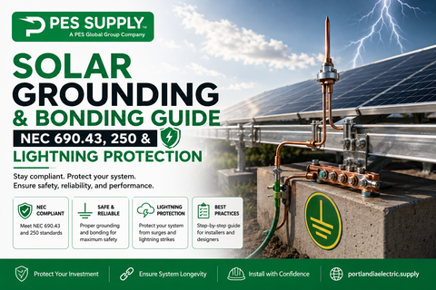
Every module frame, rail, and metallic raceway gets bonded back to the grounding system per NEC 690.43 and 250.122. The EGC doesn't carry current in normal operation — it exists to trip the breaker fast when something faults, and it's sized off the overcurrent device protecting the circuit, not the conductor.
8.1 Equipment Grounding Conductor Sizing Table (NEC 250.122)
| OCPD Rating (Amps) | Copper EGC (AWG) | Aluminum EGC (AWG) |
|---|---|---|
| 15 | 14 | 12 |
| 20 | 12 | 10 |
| 30 | 10 | 8 |
| 40 | 10 | 8 |
| 60 | 10 | 8 |
| 100 | 8 | 6 |
| 200 | 6 | 4 |
| 300 | 4 | 2 |
| 400 | 3 | 1 |
| 500 | 2 | 1/0 |
| 600 | 1 | 2/0 |
| 800 | 1/0 | 3/0 |
| 1000 | 2/0 | 4/0 |
8.2 Grounding Conductor Material
Exposed array grounding is almost always bare solid copper, 6 AWG, run with the module leads and bonded to each rail with listed lay-in lugs — WEEB or equivalent bonding washers that bite through the anodizing. One quirk worth knowing: 690.8's 125% factors don't apply to the EGC, but if you upsized the ungrounded conductors for voltage drop, 250.122(B) requires the EGC to be upsized proportionally. Our solar grounding and bonding guide covers the electrode side of the system in the same depth.
| Application | Recommended Wire Type | Typical Size | NEC Reference |
|---|---|---|---|
| Exposed module-to-module (string) | PV Wire (UL 4703) | 12–10 AWG | 690.31(C)(1) |
| Array home run to combiner/junction box | PV Wire (UL 4703) | 10–6 AWG | 690.31(C) |
| DC wiring inside building (in conduit) | PV Wire or THWN-2 in raceway | 10–2 AWG | 690.31(E) |
| AC inverter output (in conduit) | THWN-2 or XHHW-2 | 10–2/0 AWG | 310.10, 310.16 |
| Equipment grounding (exposed array) | Bare copper or PV Wire (green) | 10–6 AWG | 250.122, 690.45 |
| Equipment grounding (in conduit) | THWN-2 (green) | 14–2/0 AWG | 250.122, 690.45 |
| Grounding electrode conductor | Copper (bare or insulated) | 8 AWG min. (protected) | 250.66, 250.64(B) |
| Direct burial (ground mount home run) | USE-2/RHW-2 | 10–4 AWG | 300.5, 690.31 |
- Keep conductors off the roof surface. Clip to the rail, every 24 inches or per the clip listing. Wire sitting on shingles wicks heat, abrades, and pools water at low points.
- Respect bend radius. Five times the cable OD for PV wire; kinked fine-strand conductors break strands at the crimp.
- Positive and negative in the same raceway. Split them and inductive heating plus confusion at the pull box are your reward.
- Label both ends of everything. "STRING 3 (+)" at both the array and the combiner. Future-you, troubleshooting at dusk, will be grateful.
- Leave service loops at modules — 6 inches of slack at each MC4 so thermal cycling works the loop, not the crimp.
- Torque terminations to the lug spec, with a calibrated screwdriver or wrench. "Hand tight plus a quarter turn" is how lugs cook. Most 10–14 AWG terminations land between 20–35 in-lb — read the label on the device.
- Buy sunlight-resistant everything on the roof. Zip ties included. Standard black nylon ties outlast white ones, but listed stainless or PV-rated polymer clips outlast both.
- Megger the strings before landing them. A 10-minute insulation-resistance test catches the nicked jacket now instead of after the roof crew leaves.
Solar wiring rewards the boring virtues: the right listing, the honest derate, the extra gauge. PV wire on the array, THWN-2 in the raceways, USE-2 in the dirt, and every conductor sized for the heat it will actually see. Do the 690.8 math once on paper, and the array runs cool for decades — skip it, and you meet the inspector, the insurance adjuster, or the thermal camera, in that order. When you're ready to pull the trigger on material, the spools are on the shelf: PV wire, THHN/THWN-2.
Can I use THHN wire for solar panels?
Only inside raceways. THHN/THWN-2 is the right, economical choice for DC runs in conduit inside buildings and for AC inverter output circuits, but it carries no standard sunlight-resistance listing and NEC 690.31(C) does not permit it exposed on the array. Exposed array wiring requires PV wire or USE-2/RHW-2.
What size wire do I need for a 400-watt solar panel?
A single 400 W residential module produces roughly 10–11 A at its maximum power point, with an Isc around 11–12 A. After the NEC 690.8 multipliers (1.56 × Isc ≈ 17–19 A), 12 AWG PV wire handles one or two strings comfortably; 10 AWG is the common default because it costs little more and cuts voltage drop nearly in half. String size, run length, and rooftop temperature decide the final gauge — run the Sections 3 and 5 math, not a rule of thumb.
Is PV wire the same as USE-2?
No. PV wire is listed to UL 4703 with mandatory sunlight resistance, finer stranding, and voltage ratings up to 2,000 V. USE-2 is listed to UL 44/854 at 600 V and is approved for direct burial. USE-2 with the dual RHW-2 marking is code-legal for exposed array wiring; PV wire is the better physical product for that job and the only option above 600 V strings.
How much voltage drop is acceptable in a solar array?
Design targets: under 2% on DC source circuits, under 2% on AC feeders, under 3% total. The NEC treats voltage drop as a performance recommendation rather than a requirement, but every percent of drop is a percent of production your customer never harvests. Long ground-mount runs usually dictate 8 AWG or larger regardless of ampacity.
Do solar DC wires need to be in conduit?
Within the array boundary, no — listed PV wire or USE-2/RHW-2 may run exposed per NEC 690.31(C), secured with listed clips. Inside a building, yes: 690.31(E) requires metal raceway or MC cable from the point of penetration to the first disconnect. Many jurisdictions also require a raceway for the transition from array to building entry, so confirm with your AHJ before rough-in.
Why does NEC 690.8 multiply solar current by 1.56?
It's two stacked 125% factors, not one arbitrary number. The first 125% (690.8(A)) covers irradiance enhancement — the sun briefly delivering more than the 1,000 W/m² test condition. The second 125% (690.8(B)) is the standard continuous-load factor, since peak solar output can run three hours or more. Together they size conductors and overcurrent devices for the worst realistic case, not the nameplate.
Wire Your Next Array Right
PV wire, THHN/THWN-2, USE-2, MC4s, clips, and conduit — wholesale pricing, contractor will-call, same-day shipping on stock items.
Shop Wire & Cable