Updated September 2026 — refreshed against the live PES catalog; product pricing verified 2026-09-26.
NEC Wire Sizing Guide: Ampacity Charts for Solar and Generator Installations
Reading time: ~13 min read
📋 Key Takeaways
- NEC Table 310.16 provides allowable ampacity values for insulated conductors up to 2000V.
- Temperature correction factors must be applied based on ambient temperature.
- Conduit fill derating applies when more than three current-carrying conductors share a raceway.
- Voltage drop calculations ensure efficient power delivery (target: under 3% for feeders, 5% total).
- Wire sizing must satisfy both ampacity and voltage drop requirements.
Proper conductor sizing is the foundation of every safe solar and generator installation. Undersized wire causes excessive voltage drop, overheating, and fire risk. Oversized wire wastes money and complicates conduit fill. This guide provides electricians and solar installers with a practical reference for NEC-compliant wire sizing using Table 310.16 ampacity values, temperature correction factors, conduit fill derating, and voltage drop calculations for both solar PV and standby generator applications.
For conductor, lug, and accessory options, browse our electrical accessories collection and our conduit types guide at PES Supply.
NEC Table 310.16: The Foundation of Wire Sizing
NEC Table 310.16 provides allowable ampacity values for insulated conductors rated up to 2000 volts, in sizes from 14 AWG through 1000 kcmil. The table is organized by conductor material (copper or aluminum) and insulation temperature rating (60°C, 75°C, and 90°C columns). The values assume a 30°C (86°F) ambient temperature and no more than three current-carrying conductors in a raceway or cable.
I've been red-tagged exactly once on ampacity, and it was for trusting memory instead of opening the book — I sized a feeder off the 90°C column because the insulation said THHN-2, and the inspector walked me straight to 110.14(C). The termination rating wins every argument. Now my crews keep a laminated 310.16 card in every gang box, and nobody sizes from memory.
The table below reproduces the most commonly used ampacity values from NEC Table 310.16:
| Wire Size | Cu 60°C | Cu 75°C | Cu 90°C | Al 60°C | Al 75°C | Al 90°C |
|---|---|---|---|---|---|---|
| 14 AWG | 15 A | 20 A | 25 A | N/A* | N/A* | N/A* |
| 12 AWG | 20 A | 25 A | 30 A | 15 A | 20 A | 25 A |
| 10 AWG | 30 A | 35 A | 40 A | 25 A | 30 A | 35 A |
| 8 AWG | 40 A | 50 A | 55 A | 35 A | 40 A | 45 A |
| 6 AWG | 55 A | 65 A | 75 A | 40 A | 50 A | 55 A |
| 4 AWG | 70 A | 85 A | 95 A | 55 A | 65 A | 75 A |
| 3 AWG | 85 A | 100 A | 115 A | 65 A | 75 A | 85 A |
| 2 AWG | 95 A | 115 A | 130 A | 75 A | 90 A | 100 A |
| 1 AWG | 110 A | 130 A | 145 A | 85 A | 100 A | 115 A |
| 1/0 AWG | 125 A | 150 A | 170 A | 100 A | 120 A | 135 A |
| 2/0 AWG | 145 A | 175 A | 195 A | 115 A | 135 A | 150 A |
| 3/0 AWG | 165 A | 200 A | 225 A | 130 A | 155 A | 175 A |
| 4/0 AWG | 195 A | 230 A | 260 A | 150 A | 180 A | 205 A |
*NEC 310.16 begins aluminum ampacities at 12 AWG — 14 AWG aluminum is not a listed size, so those columns are N/A.
Values based on NEC Table 310.16 (2023 NEC). Assumes 30°C ambient and ≤3 current-carrying conductors in raceway.
Which Column to Use?
Selecting the correct column is critical and depends on the lowest temperature rating of any component in the circuit:
- 60°C column: Use when connecting to equipment rated for 60°C terminations (older equipment, some 14 AWG through 10 AWG circuits). Also the column required by NEC 110.14(C)(1)(a) for equipment rated 100 A or less, and for equipment not marked with a temperature rating.
- 75°C column: The most commonly used column. Use when all terminations and equipment are rated for 75°C. Most modern circuit breakers, lugs, and equipment are rated 75°C.
- 90°C column: Used primarily as the starting point for derating calculations (ambient temperature and conduit fill), NOT as the final allowable ampacity. The 90°C column applies only when ALL equipment in the circuit is rated 90°C, which is rare.
NEC 240.4(D) Small Conductor Limits
Regardless of the ampacity shown in Table 310.16, NEC 240.4(D) imposes maximum overcurrent protection for small conductors:
- 14 AWG copper: maximum 15 A breaker
- 12 AWG copper: maximum 20 A breaker
- 10 AWG copper: maximum 30 A breaker
- 12 AWG aluminum: maximum 15 A breaker
- 10 AWG aluminum: maximum 25 A breaker
These limits apply to general-purpose branch circuits. They do NOT apply to motor circuits (Article 430) or certain solar PV circuits where the 90°C column may be used for derating before applying the 75°C termination limit.
Temperature Correction Factors
NEC Table 310.16 ampacities are based on a 30°C (86°F) ambient temperature. For installations at different ambient temperatures, apply correction factors from NEC Table 310.15(B)(1). The correction is applied to the 90°C column ampacity (the derating starting point), then verified against the 75°C or 60°C termination limit.
| Ambient Temp (°C) | Ambient Temp (°F) | 60°C Rated | 75°C Rated | 90°C Rated |
|---|---|---|---|---|
| 21–25 | 70–77 | 1.05 | 1.05 | 1.04 |
| 26–30 | 78–86 | 1.00 | 1.00 | 1.00 |
| 31–35 | 87–95 | 0.94 | 0.96 | 0.96 |
| 36–40 | 96–104 | 0.88 | 0.91 | 0.93 |
| 41–45 | 105–113 | 0.82 | 0.87 | 0.89 |
| 46–50 | 114–122 | 0.75 | 0.82 | 0.85 |
| 51–55 | 123–131 | 0.67 | 0.76 | 0.80 |
| 56–60 | 132–140 | 0.58 | 0.71 | 0.76 |
Source: NEC Table 310.15(B)(1), 2023 NEC. For temperatures above 60°C, consult the manufacturer and the NEC.
Solar-Specific Consideration: Rooftop Temperature
Solar PV conductors installed on or near rooftops experience significantly elevated ambient temperatures. NEC 310.15(B)(2) requires an additional temperature adjustment for wiring methods installed above rooftops exposed to sunlight. Add 33°C (60°F) to the outdoor ambient temperature for conductors within 0.5 inches of the rooftop, decreasing to 0°C addition at 3.5 inches above the rooftop:
- 0 to 0.5 inches above roof: add 33°C
- 0.5 to 1.5 inches above roof: add 22°C
- 1.5 to 3.5 inches above roof: add 11°C
- Above 3.5 inches: no addition
This means a 40°C (104°F) Phoenix day with conduit mounted 0.5 inches above the roof yields a design ambient of 62°C, requiring substantial derating. Always use the 90°C-rated conductor (THWN-2, USE-2, PV Wire) as the starting point for solar circuits.
We've put a thermometer on rooftop EMT in July and read 70°C at the conduit surface — hot enough that the wire inside is living in a different world than the weather report suggests. On dark membrane roofs we now spec the rooftop adder by default and bump a wire size whenever the run sits within an inch of the deck. It costs a few dollars of copper and saves a derating argument at inspection.
Conduit Fill Derating
When four or more current-carrying conductors are installed in the same raceway or cable, NEC 310.15(C)(1) requires ampacity derating. The adjustment factors are:
| Number of Current-Carrying Conductors | Derating Factor |
|---|---|
| 1–3 | 1.00 (no derating) |
| 4–6 | 0.80 |
| 7–9 | 0.70 |
| 10–20 | 0.50 |
| 21–30 | 0.45 |
| 31–40 | 0.40 |
| 41 and above | 0.35 |
Source: NEC Table 310.15(C)(1), 2023 NEC.
What Counts as a Current-Carrying Conductor?
- Neutral conductors of 3-phase, 4-wire wye systems where the major portion of the load consists of nonlinear loads (harmonics) count as a current-carrying conductor
- Neutral conductors of single-phase, 3-wire systems count as a current-carrying conductor
- Equipment grounding conductors do NOT count
- DC conductors in solar systems: each positive and negative conductor counts as current-carrying
- A 2-wire DC circuit (one positive, one negative) = 2 current-carrying conductors
NEC Chapter 9 Conduit Fill Percentages
Separate from ampacity derating, NEC Chapter 9, Table 1 limits the physical fill of conduit:
- 1 conductor: 53% fill
- 2 conductors: 31% fill
- 3 or more conductors: 40% fill
Use NEC Chapter 9, Table 5 (conductor areas) and Table 4 (conduit internal areas) to calculate fill. For THHN/THWN conductors in EMT, the maximum number of conductors per trade size is well documented in NEC Annex C, Table C.1.
Combined Derating: Temperature + Conduit Fill
When both temperature correction and conduit fill derating apply, calculate them as a compound derating using the 90°C column as the starting point, then verify the result does not exceed the termination limit (75°C column for modern equipment).
Worked Example
A solar combiner box feeds eight #10 AWG THWN-2 copper conductors (4 PV circuits) in a single conduit mounted 0.5 inches above a rooftop in a 40°C ambient environment.
- Step 1: Start with 90°C column ampacity: #10 Cu THWN-2 = 40 A
- Step 2: Rooftop temperature adjustment: 40°C + 33°C = 73°C design ambient
- Step 3: Temperature correction factor at 73°C (interpolate between 71–75°C row): approximately 0.52
- Step 4: Conduit fill derating for 8 current-carrying conductors: 0.70
- Step 5: Compounded ampacity: 40 A × 0.52 × 0.70 = 14.56 A
- Step 6: Verify against 75°C termination limit: 35 A (passes)
- Result: The #10 AWG conductor is limited to approximately 15 A after derating
If the calculated circuit current exceeds the derated ampacity, upsize the conductor. This is why solar PV installations frequently require larger conductors than the nameplate current would suggest.
Voltage Drop Calculations
NEC does not mandate a specific voltage drop limit, but it recommends a maximum of 3% on branch circuits and 5% total (feeder + branch) for efficient operation. Excessive voltage drop causes motors to draw more current (heating), reduces solar PV system yield, and can cause nuisance tripping on generator installations.
Voltage Drop Formulas
Single-phase (2-wire):
VD = (2 × K × I × D) ÷ CM
Three-phase:
VD = (1.732 × K × I × D) ÷ CM
Where:
- VD = voltage drop in volts
- K = 12.9 for copper, 21.2 for aluminum (resistance in ohms per circular mil-foot)
- I = current in amps (use the larger of continuous load or 125% of continuous load per NEC 210.19)
- D = one-way distance in feet
- CM = circular mil area of the conductor (see NEC Chapter 9, Table 8)
Percentage Voltage Drop
VD% = (VD ÷ System Voltage) × 100
Common Circular Mil Areas
| Wire Size | Circular Mils (CM) |
|---|---|
| 14 AWG | 4,107 |
| 12 AWG | 6,530 |
| 10 AWG | 10,380 |
| 8 AWG | 16,510 |
| 6 AWG | 26,240 |
| 4 AWG | 41,740 |
| 2 AWG | 66,360 |
| 1/0 AWG | 105,600 |
| 4/0 AWG | 211,600 |
Source: NEC Chapter 9, Table 8.
Worked Example: Generator Feeder
A 20 kW, 240V single-phase generator is located 150 feet from the transfer switch. The continuous load is 83 A. What size copper conductor keeps voltage drop under 3%?
- Maximum allowable VD = 240V × 0.03 = 7.2V
- Required CM = (2 × 12.9 × 83 × 150) ÷ 7.2 = 44,625 CM
- The next standard size above 44,625 CM is 3 AWG (52,620 CM)
- Verify ampacity: 3 AWG Cu at 75°C = 100 A > 83 A × 1.25 = 104 A—upsizing to 2 AWG (115 A) is needed for continuous load
- Select 2 AWG copper THWN-2 for this application
Quick Reference: Generator Feeder Sizing (240V Single-Phase, Continuous)
The table below applies NEC 445.13 (115% nameplate) and the 125% continuous-load factor together, then selects the minimum copper conductor at 75°C terminations. Aluminum equivalents run roughly two sizes larger. Always confirm voltage drop on runs over 100 feet — long feeders often force the next size up regardless of ampacity.
| Generator Size | Full-Load Amps (240V 1-ph) | Required Ampacity (×1.25 continuous) | Min Cu THWN-2 (75°C) | Min Al XHHW-2 (75°C) |
|---|---|---|---|---|
| 10 kW | 41.7 A | 52.1 A | 6 AWG (65 A) | 4 AWG (65 A) |
| 14 kW | 58.3 A | 72.9 A | 4 AWG (85 A) | 2 AWG (90 A) |
| 20 kW | 83.3 A | 104.2 A | 2 AWG (115 A) | 1/0 AWG (120 A) |
| 22 kW | 91.7 A | 114.6 A | 1 AWG (130 A) | 2/0 AWG (135 A) |
| 24 kW | 100 A | 125 A | 1/0 AWG (150 A) | 3/0 AWG (155 A) |
| 30 kW | 125 A | 156.3 A | 2/0 AWG (175 A) | 4/0 AWG (180 A) |
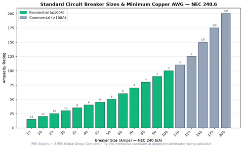
Ampacities from NEC Table 310.16 (2023 NEC), 75°C column. Verify against NEC 240.4, 445.13, and the transfer switch listing — our standard breaker sizes chart covers the OCPD side, and the generators collection lists the units these feeders serve.
Copper vs Aluminum Conductors
The choice between copper and aluminum conductors involves cost, weight, installation practicality, and termination compatibility:
| Characteristic | Copper | Aluminum |
|---|---|---|
| Conductivity | 100% IACS (baseline) | 61% IACS |
| Size for same ampacity | Smaller (baseline) | ~2 AWG sizes larger |
| Weight | Heavier | ~30% of copper weight |
| Cost per amp | Higher | Lower (typically 30–50% less) |
| Termination compatibility | Direct to most lugs | Requires AL-rated lugs or CU/AL bifurcated connectors |
| Thermal expansion | Lower | Higher (requires compatible connectors) |
| Common sizes | 14 AWG – 4/0+ | 6 AWG – 1000 kcmil |
| Typical application | Branch circuits, solar PV DC, generator feeders <100 ft | Service entrances, long generator feeders, large PV array feeders |
My standing rule on service and feeder pulls: copper for anything under 100 feet, aluminum only when the run or the ampacity makes the copper price hurt. I've re-torqued enough aluminum lugs after their first summer to respect the thermal cycle — antioxidant compound and a torque wrench aren't optional, they're the difference between a 30-year connection and a service call with a burnt lug.
Aluminum Installation Considerations
- Use only AA-8000 series alloy aluminum conductors (NEC 310.10(B))
- Apply antioxidant compound to all aluminum connections
- Verify lugs are marked AL/CU or CU/AL—never connect aluminum to copper-only lugs
- Torque all connections to manufacturer specifications and re-torque after thermal cycling
- Use listed connectors rated for aluminum conductors
- Aluminum is not recommended for small conductors (below 6 AWG) due to thermal expansion issues
Solar PV Wire Sizing (NEC Article 690)
Solar PV installations have specific conductor requirements under NEC Article 690:
- 690.8 Circuit Sizing: PV circuit conductors must be sized to carry not less than 125% of the maximum current (Isc × 1.56 for older code editions, Isc × 1.25 under 2023 NEC) before applying continuous load and derating factors
- 690.7 Voltage Rating: Conductors must be rated for the maximum PV system voltage (calculated at the lowest expected ambient temperature using module Voc temperature coefficient)
- 690.31 Conductor Types: PV Wire or USE-2 required for exposed module interconnections; THWN-2 acceptable in conduit for home runs and combiner outputs
- 690.8(A)(1) Maximum Current: For PV source circuits: Isc × 1.25; for PV output circuits: Isc × 1.25 (2023 NEC)
For the cable itself, our PV Wire vs. USE-2 vs. THHN guide breaks down insulation selection, and the conduit fill chart keeps the raceway side honest once those derated home runs get bundled. EV charger circuits follow the same 125% continuous logic — see the EV charger circuit and breaker size chart for that application.
PV Circuit Sizing Example
A string of modules has a rated Isc of 9.5 A. The conductors run through conduit on a rooftop with 6 other current-carrying conductors, at a design ambient of 60°C.
- Maximum PV circuit current: 9.5 A × 1.25 = 11.88 A
- Continuous load factor: × 1.25 = 14.85 A required ampacity
- Temperature correction at 60°C (90°C column): 0.76
- Conduit fill for 7 current-carrying conductors: 0.70
- Required 90°C ampacity: 14.85 ÷ (0.76 × 0.70) = 27.9 A
- #10 AWG Cu THWN-2 (40 A at 90°C) satisfies this requirement
- Verify 75°C termination: 35 A > 14.85 A—passes
Generator Feeder Sizing (NEC Article 445)
NEC Article 445 governs generator installations:
- 445.13 Ampacity of Conductors: Generator conductors must have an ampacity not less than 115% of the generator nameplate current rating
- 445.18 Disconnect: A disconnecting means must be provided for the generator output
- 445.19 Signs: A sign indicating generator type, voltage, and current must be posted
For continuous loads (running for 3+ hours), apply the 125% continuous load factor per NEC 210.19(A)(1). Generator feeders frequently carry continuous load, so this factor is commonly applied.
Generator Feeder Example
A 30 kW, 240V single-phase generator has a nameplate current of 125 A.
- Minimum conductor ampacity: 125 A × 1.15 = 143.75 A
- With 75°C terminations: 1/0 AWG Cu (150 A) or 3/0 AWG Al (155 A)
- For continuous operation: 125 A × 1.25 = 156.25 A required
- Select 2/0 AWG Cu (175 A) or 4/0 AWG Al (180 A) for continuous-rated installations
Conductor Insulation Types Reference
| Insulation Type | Max Temp | Common Uses |
|---|---|---|
| THHN/THWN-2 | 90°C dry / 90°C wet | General building wire in conduit, solar home runs |
| XHHW-2 | 90°C dry / 90°C wet | Generator feeders, service entrances, wet locations |
| USE-2 / RHH / RHW-2 | 90°C | Solar PV exposed wiring, underground service |
| PV Wire (Type PV) | 90°C wet / 150°C dry | Solar module interconnections, exposed PV wiring |
| MTW | 90°C | Machine tool wiring, control circuits |
Wire Sizing Checklist
- Determine the continuous and non-continuous load current
- Apply 125% factor for continuous loads (NEC 210.19)
- Apply 115% factor for generator feeders (NEC 445.13)
- Apply 125% factor for PV circuits (NEC 690.8)
- Select the correct temperature column based on termination ratings
- Apply ambient temperature correction (NEC 310.15(B)(1))
- Apply rooftop temperature addition for solar installations (NEC 310.15(B)(2))
- Apply conduit fill derating for 4+ current-carrying conductors (NEC 310.15(C)(1))
- Calculate voltage drop for long runs; upsize if exceeding 3% branch / 5% total
- Verify final ampacity against NEC 240.4(D) small conductor limits
- Verify conduit fill per NEC Chapter 9, Table 1
- Verify conductor insulation type is suitable for the environment (wet, dry, sunlight, burial)
Conclusion
Proper wire sizing requires working through a systematic process: determine load current, select the correct NEC Table 310.16 column, apply temperature and conduit fill derating, check voltage drop on long runs, and verify the final selection against all applicable code sections. Solar PV installations add additional complexity through rooftop temperature additions and Article 690 circuit sizing rules. Generator installations require Article 445 compliance and attention to continuous load factors. By following this methodology, installers ensure safe, code-compliant, and efficient conductor selection for every application.
Shop conductors, lugs, and accessories in our electrical accessories collection, and find the right raceway in our electrical supplies collection. For generator packages and transfer switches, visit our generators collection. Standard delivery is 7-10 business days.
Frequently Asked Questions
How do I size wire using NEC Table 310.16?
Determine the load current, then find the minimum wire gauge in Table 310.16 that can carry that current at the appropriate temperature rating. Apply correction factors for ambient temperature and conduit fill derating. Finally, verify the voltage drop is within acceptable limits.
What is the 3% voltage drop rule?
NEC recommends a maximum voltage drop of 3% on feeders and 3% on branch circuits, for a total of 5% from service entrance to the load. While not strictly mandatory, exceeding these limits can cause equipment malfunction, reduced efficiency, and motor overheating.
How do I apply temperature correction factors?
NEC Table 310.16 ampacity values are based on 30C ambient. For other temperatures, use the correction factors in the table notes. At 40C, most conductor ampacities are reduced by about 5-8%. At 50C, reductions of 12-15% apply.
What is conduit fill derating?
When more than three current-carrying conductors are installed in the same conduit or raceway, their ampacity must be derated per NEC Table 310.15(C)(1). For 4-6 conductors, derate to 80%; for 7-9, derate to 70%; for 10-20, derate to 50%.
What wire size do I need for a 50A circuit at 100 feet?
For a 50A load at 100 feet on a 240V circuit, #6 AWG copper satisfies ampacity requirements. However, voltage drop at this distance may require upsizing to #4 AWG to stay within the 3% limit. Always verify both ampacity and voltage drop.
Ready to Source Your Equipment?
Browse 50,000+ SKUs from 169 authorized brands. Trade pricing with full OEM warranties.
Shop All Categories Request a QuoteShop This Article
Ready to build your system? PES Supply stocks 50,000+ SKUs from 169 authorized brands, with delivery in 7-10 business days. Here are the products mentioned in this article:
- BR Solar Group BR-M310W
- Schneider Conext Gateway PRO
- Siemens GNF221RA 30A Safety Disconnect
- BR Solar Group BR-M315W
- MidNite Conext SW Back Plate (MNSW-BP)
Browse all electrical · Browse all circuit breakers · Surge protection sizing guide
Related Articles
- Electrical Conduit Types: PVC vs. EMT vs. RMC for Solar Installations
- Surge Protection for Solar Systems: SPD Sizing and Installation Guide
- Solar Grounding and Bonding Guide: NEC 690.43, 250, and Lightning Protection
- Solar Disconnect and Overcurrent Protection Guide: NEC 690 Requirements Explained
Related: 22 AWG Wire Ampacity & NEC Compliance — chassis wiring ratings, Class 2/3 power-limited circuits, and gauge comparison.