Voltage drop is the silent killer of otherwise well-designed electrical systems. A run of wire that looks fine on paper can leave the motor at the far end starved of voltage, running hot, tripping overloads, and dying years early. The National Electrical Code doesn't set a hard legal limit for voltage drop on branch circuits, but the NEC's informational notes (210.19(A) Informational Note No. 4 and 215.2(A)(1) Informational Note No. 2) point designers to the same targets the industry has used for decades: keep a branch circuit under 3% and keep the total of feeder plus branch under 5%. This guide gives you a working calculator, the actual math, and the reference tables to check any run by hand.
If you already know your ampacity requirement and just need the wire size, our Wire Ampacity Calculator (NEC 310.16) handles that side of the problem. Voltage drop and ampacity are separate checks — a conductor can pass one and fail the other — and both must pass before you pull wire.
Voltage Drop Calculator
NEC 3% branch-circuit / 5% combined guidance · single-phase & three-phase · copper & aluminum
Method: VD = 2·K·L·I ÷ circular mils (single-phase); VD = √3·K·L·I ÷ CM (three-phase). K = 12.9 Ω·cmil/ft for copper, 21.2 for aluminum at 75 °C. Always confirm ampacity per NEC 310.16 and breaker sizing per the 125% rule.
The Voltage Drop Formula, Explained Plainly
Every conductor is a resistor. Push current through it and some of the system voltage is spent overcoming that resistance instead of doing useful work at the load. The standard single-phase formula used throughout the industry is:
VD = 2 × K × L × I ÷ CM
where L is the one-way conductor length in feet (the "2" accounts for the round trip out and back), I is load current in amps, CM is the conductor's cross-sectional area in circular mils, and K is the resistivity constant: approximately 12.9 ohm-circular-mils per foot for copper and 21.2 for aluminum at 75 °C. For three-phase systems the round-trip geometry changes, so the multiplier is √3 instead of 2:
VD3φ = 1.732 × K × L × I ÷ CM
To express the drop as a percentage — the number the NEC guidance actually references — divide by the system voltage and multiply by 100. A 7.2 V drop means very different things on a 120 V circuit (6%) and a 480 V circuit (1.5%), which is why percentage, not volts, is the design criterion.
Worked Example 1: A 240 V Well Pump That Barely Passes
A 240 V single-phase well pump draws 30 A and sits 150 feet from the panel. An installer reaches for 10 AWG copper because the NEC 310.16 ampacity chart says 10 AWG copper handles 35 A at 75 °C. Ampacity passes. Now check the drop:
VD = 2 × 12.9 × 150 × 30 ÷ 10,380 = 11.18 V = 4.66%
That fails the 3% branch guideline even though the wire is perfectly safe from an overheating standpoint. Stepping up to 8 AWG copper (16,510 cmil) gives VD = 7.02 V = 2.93% — a pass. This is the classic long-run trap: on short runs ampacity governs, on long runs voltage drop governs, and the crossover happens sooner at lower voltages.
Worked Example 2: Three-Phase 480 V Feeder
A 480 V three-phase load draws 100 A over a 200-foot run using 3/0 aluminum (167,800 cmil):
VD = 1.732 × 21.2 × 200 × 100 ÷ 167,800 = 4.38 V = 0.91%
Comfortably under 3% — higher system voltages are far more forgiving, which is exactly why commercial distribution runs at 480 V and long solar strings run at 600–1000 V. If you're designing PV source circuits, our PV wire voltage options guide and the MC4 wire gauge guide cover the DC side, where 2% is the common design target.
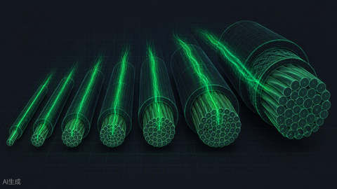
Conductor Reference: Circular Mils by Size
The calculator above uses these NEC Chapter 9, Table 8 values. Print it, save it, or just trust the tool:
| Size | Circular mils | Size | Circular mils |
|---|---|---|---|
| 14 AWG | 4,110 | 2/0 AWG | 133,100 |
| 12 AWG | 6,530 | 3/0 AWG | 167,800 |
| 10 AWG | 10,380 | 4/0 AWG | 211,600 |
| 8 AWG | 16,510 | 250 kcmil | 250,000 |
| 6 AWG | 26,240 | 350 kcmil | 350,000 |
| 4 AWG | 41,740 | 500 kcmil | 500,000 |
| 2 AWG | 66,360 | 750 kcmil | 750,000 |
Maximum One-Way Run for a 3% Drop (Copper, Common Cases)
This table shows how fast voltage drop eats your budget at 120 V versus 240 V. Values are one-way feet for copper conductors at full load:
| Load | Wire | Max run @120 V (3%) | Max run @240 V (3%) |
|---|---|---|---|
| 15 A | 14 AWG Cu | 47 ft | 93 ft |
| 20 A | 12 AWG Cu | 56 ft | 112 ft |
| 20 A | 10 AWG Cu | 89 ft | 178 ft |
| 30 A | 10 AWG Cu | 59 ft | 119 ft |
| 30 A | 8 AWG Cu | 95 ft | 189 ft |
| 40 A | 8 AWG Cu | 71 ft | 142 ft |
| 50 A | 6 AWG Cu | 90 ft | 180 ft |
| 100 A | 2 AWG Cu | 114 ft | 228 ft |
The pattern is unmistakable: doubling the system voltage doubles the allowable distance, and dropping from 240 V to 120 V halves it. For long outbuilding or gate-operator runs, stepping up to 240 V (or 480 V three-phase) is often cheaper than buying thicker copper.
Maximum One-Way Run for a 3% Drop (480 V Three-Phase, Copper)
Commercial feeders at 480 V three-phase get enormous distance budgets because the percentage denominator is large and the 1.732 multiplier beats the single-phase 2×. One-way feet at full load:
| Load | Wire (Cu) | Max run @480 V 3φ (3%) | Max run @208 V 3φ (3%) |
|---|---|---|---|
| 50 A | 6 AWG | 451 ft | 196 ft |
| 100 A | 2 AWG | 570 ft | 247 ft |
| 150 A | 2/0 AWG | 633 ft | 274 ft |
| 200 A | 4/0 AWG | 760 ft | 329 ft |
| 300 A | 350 kcmil | 839 ft | 363 ft |
| 400 A | 500 kcmil | 900 ft | 389 ft |
At 480 V, a 200 A load can travel three-quarters of a football field on 4/0 copper before drop becomes a design constraint. At 208 V the same wire is spent at 329 feet — one reason 208 V wye services deserve closer scrutiny on spread-out commercial sites.
Feeder vs. Branch: Splitting the 5% Budget
The 5% figure is a combined allowance: feeder plus branch together. In practice designers allocate it deliberately — a common split is 2% to the feeder and 3% to the branch, but any split that sums to 5% works. On a long service to a detached building, it often makes sense to give the feeder 2.5–3% (one fat efficient run) and leave 2–2.5% for branch circuits inside the building. Run the calculator twice — once for the feeder segment, once for the branch — and add the percentages. Forgetting that the budget is shared is how a building full of individually compliant circuits ends up with dimming lights at the end of the line.
Constants Quick Card
| Constant | Value | When to use it |
|---|---|---|
| K — copper | 12.9 Ω·cmil/ft | All copper voltage-drop work at 75 °C |
| K — aluminum | 21.2 Ω·cmil/ft | All aluminum voltage-drop work at 75 °C |
| Single-phase multiplier | 2 | 120/240 V split-phase circuits (round trip) |
| Three-phase multiplier | 1.732 (√3) | 208/240/480 V balanced three-phase, line-to-line volts |
| Branch-circuit target | ≤3% | Panel to final load |
| Combined target | ≤5% | Feeder + branch added together |
| Solar DC design target | ≤1.5–2% | PV strings — stricter than NEC guidance |
Copper vs. Aluminum: The 21.2 vs. 12.9 Trade-Off
Aluminum's K constant is about 64% higher than copper's, so for the same size and load, aluminum drops roughly 1.64× the voltage. The practical rule of thumb is to go two sizes larger when you switch from copper to aluminum — 2 AWG aluminum behaves approximately like 4 AWG copper on voltage drop. Aluminum still wins on cost and weight for feeders over about 100 A, which is why it dominates service entrance and large feeder work. For branch circuits under 50 A, copper's compactness and termination simplicity usually justify the premium. Either way, buy from a traceable mill source — our Cerro Wire inventory and the broader THHN collection carry the common branch and feeder sizes, and the PV wire vs. USE-2 vs. THHN guide explains which insulation types survive which environments.
Common Voltage Drop Mistakes (Seen in the Field)
- Using one-way length without the round trip. The formula's "2" is not optional. Forgetting it makes every 120 V calc look twice as good as reality.
- Checking ampacity only. A 10 AWG run that passes 310.16 can still deliver 4–5% drop at 150 feet. Ampacity keeps insulation from melting; voltage drop keeps motors from cooking. Different failure modes, different checks.
- Sizing for breaker rating instead of actual load. Voltage drop depends on real operating current. A 20 A breaker feeding a 12 A actual load only drops voltage on 12 A — but if the load is continuous and may grow, design to the breaker.
- Ignoring the feeder share of the 5% budget. If the feeder to your subpanel already drops 2%, the branch circuit only has 3% left for a 5% total — the NEC's informational-note targets stack.
- Forgetting motor starting current. Locked-rotor current is 5–7× running current. A run that passes at full load can still sag hard enough at start to drop contactors or stall the compressor. Long motor feeds deserve extra margin or a soft start.
- Mixing up 208 V and 240 V. At 208 V the same absolute drop is a bigger percentage. Three-phase 208 V wye systems need their own check, not a 240 V assumption.
When Voltage Drop Changes the Whole Design
Sometimes the right answer isn't a bigger wire. Options worth pricing before you commit to 500 kcmil copper: move the panel or transformer closer to the load, step up to a higher distribution voltage, split the load across two smaller parallel runs (permitted at 1/0 and larger under 310.10(G) with strict symmetry rules), or — for solar and battery systems — locate the inverter at the array and run AC instead of long DC strings. Our NEC wire sizing guide for solar and generator installations walks through those system-level trade-offs, and the conduit fill chart tells you whether the upsized conductors still fit the raceway you planned. Once the wire is sized, match the overcurrent device using the breaker sizing 125% rule and verify the breaker itself in our circuit breaker inventory.
Working the other side of a battery-based system? Long inverter-to-panel runs matter there too — pair this tool with the Battery Runtime Calculator and the Solar Panel Sizing Calculator to size the whole chain from array to load.
Frequently Asked Questions
Is the 3% voltage drop rule actually enforceable code?
No. NEC 210.19(A) and 215.2(A)(1) express the 3%/5% figures in informational notes, which are recommendations, not mandates. However, many inspectors treat them as the de facto standard, equipment warranties often assume them, and some jurisdictions and project specifications adopt them as hard requirements. Designing to 3%/5% is the safe default everywhere.
What K value should I use — 12.9 or 12.56 for copper?
Both appear in the literature. K = 12.9 Ω·cmil/ft is the standard value at 75 °C conductor temperature, matching loaded conductors sized per the 75 °C column of 310.16. K = 12.56 applies at 25 °C. Using 12.9 is slightly conservative, which is the correct direction for design.
Does voltage drop matter for solar PV DC strings?
Yes — arguably more, because every volt dropped on the DC side is energy your inverter never converts. The solar industry commonly designs to 1.5–2% total DC drop. High string voltages (600–1000 V) make this easy; long low-voltage battery bank cables at 12–48 V are where DC drop becomes brutal.
Why does my three-phase calculation use 1.732 instead of 2?
In a balanced three-phase circuit, current returns through the other phases rather than a dedicated neutral, so the effective loop geometry changes. The √3 (1.732) multiplier applied to line-to-line voltage produces the correct percentage drop. Use it with the line-to-line system voltage (208, 240, or 480 V).
Should I size for the motor's starting current?
Not for the steady-state drop calculation — size for running current against 3%. But do verify that the sag during starting (5–7× running amps for a few seconds) won't drop out contactors, dim lights excessively, or stall the motor. Long motor feeders often get one extra size for exactly this reason.
What if no single conductor gets me under 3%?
Above roughly 750 kcmil the options are parallel conductor runs (1/0 AWG minimum, per NEC 310.10(G), with identical length, material, and termination), a higher system voltage, or relocating the source closer to the load. At that scale, have the design stamped by an engineer and get the conductor package quoted as a bundle.
Shop the products mentioned in this guide and get everything you need for your project.

Service Wire 10 AWG 1000V Solar PV Wire 500' Red - 10PV1000VREDX500
Service Wire
$337.00
View Product