Last Updated: September 2026 • A Design Reference for Installers, Designers, and Project Developers
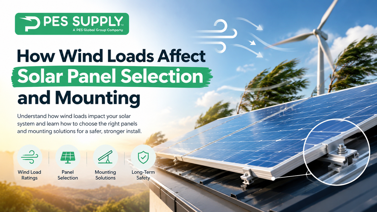
A solar array is, structurally, a large flat surface bolted to the outside of a building or planted in an open field — which is exactly the kind of object wind likes to act on. In a high-wind event, the dominant force on a rooftop array is usually not the wind pushing panels down but uplift: wind flowing over and under the modules creates suction that tries to peel the array off the roof. Failures in storms rarely start with a broken panel; they start with an attachment that pulls out, a clamp that slips, or a ballast layout that wasn't engineered for the roof zone it sits in.
This guide explains how wind loads are determined, what the module load ratings on a datasheet actually mean, how roof zones and exposure change the loads, and how to match panel selection and mounting method to the wind environment of a specific site.
⚡ Quick Answer
Design wind loads on a PV array depend on basic wind speed, exposure category, building height, roof zone, array tilt, and distance from roof edges — and are determined using ASCE 7 (or the locally adopted building code) rather than by a rule of thumb. Modules are tested to standard mechanical loads (commonly 2,400 Pa front and rear, with 5,400 Pa front ratings for snow-capable modules), but the real constraint is usually the mounting system and attachments: rail span, attachment spacing, fastener embedment, clamp location, and — on flat roofs — ballast weight and tested aerodynamic performance. Edge and corner roof zones see significantly higher uplift than the field of the roof, so attachments are often denser there. High-wind regions need higher-rated modules, closer attachment spacing, and engineered or product-approved racking; the final design should be verified by the racking manufacturer's tool or a licensed engineer.
Key Takeaways
- Uplift Is the Governing Wind Load on Most Rooftop Arrays: suction, not downward pressure, is what tears systems off roofs — so attachment pullout and clamp capacity usually control the design.
- Wind Load Is Site-Specific: basic wind speed, exposure category (open terrain vs. suburban vs. coastal), building height, and roof geometry all change the design pressure.
- Roof Edges and Corners See the Highest Loads: pressure zones near perimeters and corners can be several times higher than the field of the roof, which is why attachment spacing tightens there.
- Module Ratings Are Test Loads, Not Unlimited Capacity: a 2,400 Pa or 5,400 Pa rating comes from standardized testing, and the usable design load is lower after a safety factor — and only valid when the module is clamped in the manufacturer's approved zones.
- Clamp Location Matters as Much as Module Rating: clamping outside the manufacturer's permitted zones can void the load rating and the warranty.
- Ballasted Flat-Roof Systems Need Tested Aerodynamics: ballast requirements come from wind tunnel testing or engineered analysis for the specific racking, not from a generic weight rule.
- Larger-Format Modules Catch More Wind: bigger modules mean larger tributary areas per clamp and per attachment, so spans and spacing need to be re-checked when upsizing.
- PES Supply: rated modules, UL 2703 racking, ground-mount hardware, and attachment components in stock, with support matching equipment to the wind and snow conditions of your site.
In This Guide
- How Wind Acts on a Solar Array
- The Inputs That Determine Design Wind Load
- Roof Zones: Why Edges and Corners Matter
- Module Load Ratings: What the Datasheet Actually Means
- Wind-Driven Panel Selection
- Pitched-Roof Mounting: Attachments and Rail Spans
- Flat-Roof and Ballasted Systems
- Ground Mounts and Trackers
- High-Wind and Hurricane Regions
- Wind and Snow Together
- Wind Design Checklist
- Frequently Asked Questions
How Wind Acts on a Solar Array
Wind loads on a PV array come from pressure differences between the top and underside of the modules. On a rooftop array mounted close to the roof surface, wind can flow into the gap beneath the panels, pressurizing the underside while turbulence and flow separation create suction on the top surface. The net result is upward force on the array, along with drag and, for tilted systems, additional lateral loading.
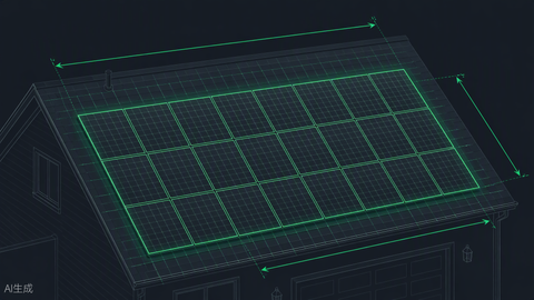
Several characteristics influence how severe those forces are: how high the array sits above the roof, the gap between modules and roof surface, the tilt angle, whether there are parapets or other shielding features, and where the array sits relative to roof edges. This is why two arrays with identical modules on identical roofs can have meaningfully different wind demands depending on layout.
The Inputs That Determine Design Wind Load
In the United States, wind loads on rooftop solar are generally determined using ASCE 7 as adopted through the local building code, which includes provisions specific to rooftop PV systems on buildings. The exact calculation is a job for the racking manufacturer's design tool or a licensed engineer, but understanding the inputs helps installers anticipate when a site will be demanding.
| Input | What It Represents | Effect on Design Load |
|---|---|---|
| Basic Wind Speed | Design gust speed for the location and risk category, from code maps | Pressure scales roughly with the square of wind speed — a modest speed increase raises loads substantially |
| Exposure Category | Surrounding terrain: B (urban/suburban, obstructed), C (open terrain), D (flat, unobstructed, near open water) | Open and coastal exposures produce higher pressures than sheltered terrain |
| Building Height | Mean roof height above ground | Wind speeds increase with height, so taller buildings see higher loads |
| Roof Geometry and Slope | Flat, gable, hip, and pitch angle | Determines roof pressure zones and their magnitudes |
| Array Tilt and Height Above Roof | How far the modules sit from the roof surface and at what angle | Flush-mounted arrays and tilted arrays respond differently; tilted arrays generally face higher loads |
| Topography | Hills, ridges, and escarpments that accelerate wind | Sites on ridges or hilltops can see amplified speeds |
| Risk Category | Importance of the structure (e.g., standard vs. essential facilities) | Higher risk categories use higher design wind speeds |
📐 Why Wind Speed Matters So Much (Illustrative)
Velocity pressure is proportional to the square of wind speed. Using a simplified relationship (approximately 0.00256 × V² × exposure/height factors) with an exposure factor near 0.85:
At 115 mph: about 29 psf of velocity pressure. At 150 mph: about 49 psf — roughly 70% higher for a 30% increase in wind speed.
Design pressures on the array are then this velocity pressure multiplied by pressure coefficients that depend on roof zone and array geometry. This example is for intuition only and is not a substitute for a code-compliant calculation.
Roof Zones: Why Edges and Corners Matter
Wind pressures are not uniform across a roof. Airflow separates at roof edges, ridges, and corners, creating localized high-suction zones. Building codes divide roofs into zones — typically an interior or field zone, an edge zone along the perimeter, and a corner zone — with progressively higher uplift coefficients toward the perimeter. The width of the edge and corner zones is generally a function of building dimensions and height.
For installers, the practical consequences are straightforward: modules near the roof perimeter and corners are exposed to the highest uplift, so racking designs commonly use closer attachment spacing, shorter rail spans, or additional ballast in those zones. Some designers also set arrays back from roof edges, which moves the array out of the highest-pressure zones and can simplify the attachment design. Always use the racking manufacturer's layout tool or engineered drawings, which account for zone-specific loads.
Module Load Ratings: What the Datasheet Actually Means
Module datasheets typically list mechanical load ratings determined by standardized testing (IEC 61215 and related UL standards). Common ratings are 2,400 Pa for wind-type loading (front and rear) and 5,400 Pa for front-side snow loading on modules built for heavier snow regions. Higher-spec products may list rear-side or front-side values above these.
| Rating | Approximate Equivalent | Typical Meaning |
|---|---|---|
| 2,400 Pa | ~50 psf | Standard test load for wind-type loading on the front and rear surfaces |
| 5,400 Pa | ~113 psf | Elevated front-side test load, commonly for snow-capable modules |
⚠ Test Load Is Not Design Load
The rated values are test loads. Many designers apply a safety factor (commonly 1.5) to convert a test load into an allowable design load, which means a 2,400 Pa test rating corresponds to a lower usable design pressure. Importantly, the rating only holds when the module is mounted using the manufacturer's approved clamp locations and methods — clamping outside those zones, or using unapproved hardware, can invalidate the rating and the warranty. Always check the module's installation manual for the exact mounting configurations and load values that apply.
Wind-Driven Panel Selection
For most sites, standard-rated modules paired with correctly engineered racking meet the wind requirements. But in demanding environments, module selection becomes part of the solution:
- Choose modules with higher mechanical ratings where loads are high. Higher front/rear ratings and robust frames provide margin in hurricane-prone, coastal, or high-exposure sites.
- Check which mounting configurations carry the rating. Some modules achieve their highest rating only with specific clamp positions (for example, clamping on the long sides near the quarter points versus the short sides). Pick a layout that uses the highest-rated configuration if the site demands it.
- Consider frame and glass construction. Thicker frames, reinforced cross-members, and heavier glass can improve resistance to deflection under load, though they add weight and cost.
- Be cautious with larger-format modules. Larger modules present more surface area per clamp and per attachment. When upsizing from a smaller module, re-verify rail spans, attachment spacing, and clamp zones rather than assuming the previous layout still works.
- Bifacial and glass-glass modules have their own installation constraints. Follow manufacturer guidance on clamping and support, as rear-glass construction can change allowable mounting configurations.
Pitched-Roof Mounting: Attachments and Rail Spans
On pitched residential roofs, the load path runs from the module through the clamps to the rails, then through the roof attachments (feet or standoffs) into the roof structure. The weakest link in that chain is often the attachment to the structure rather than the module or rail. Key factors include:
- Attachment spacing: closer spacing reduces the tributary area and load per attachment. Spacing typically tightens in edge and corner zones and in higher wind or snow regions.
- Fastener type and embedment: lag screws or structural screws need adequate embedment depth into rafters or structural members, with pullout capacity that depends on wood species, fastener diameter, and embedment. Fasteners that miss the rafter or sit in decayed wood provide little capacity.
- Rail span and cantilever: longer spans between attachments increase bending demand on the rail and the load per attachment; manufacturers publish maximum spans and cantilever limits by load condition.
- Roof condition and structure: rafter size and spacing, sheathing condition, and roof age affect pullout capacity and should be verified, particularly on older roofs.
- Waterproofing: attachments penetrate the roof, so flashing and sealing details need to withstand the same loads and weather exposure as the array.
Most major racking manufacturers provide online design tools that take site wind speed, exposure, roof geometry, and module data and return attachment spacing, rail selection, and layout. Using the manufacturer's tool, and keeping to its published limits, is the most reliable path to a compliant design on typical residential roofs.
Flat-Roof and Ballasted Systems
Flat commercial roofs often use ballasted racking, which resists wind through weight (and sometimes aerodynamic design) rather than through structural attachments, preserving the roof membrane. Wind design for these systems is more specialized:
- Aerodynamic performance is tested, not guessed. Ballast requirements typically come from wind tunnel testing or engineering analysis of the specific racking, tilt, and layout. Low-tilt, aerodynamically shaped systems with wind deflectors can reduce uplift and ballast demand.
- Roof zone matters. Ballast is typically heaviest in perimeter and corner zones and lighter in the interior, so the ballast map often varies across the roof.
- Structural capacity must support the added weight. A roof must be able to carry the array plus ballast, which is a structural engineering question — especially on older buildings or lightweight roof decks.
- Mechanical attachment may be used in combination. Where ballast alone would exceed roof capacity, hybrid designs add mechanical attachments in high-load zones.
- Setbacks and parapets help. Placing arrays away from edges, or taking advantage of parapets, can reduce wind demand.
Ground Mounts and Trackers
Ground-mounted arrays are fully exposed, with wind acting on both faces of tilted modules and on the supporting structure. Foundation design — driven piles, helical piles, concrete piers, or ballasted bases — must resist overturning, uplift, and lateral loads based on soil conditions as well as wind. A geotechnical assessment (or at least pile testing) is common on larger projects because soil strength can vary significantly across a site.
Single-axis trackers add another consideration: they are typically designed to move to a protective stow position in high winds, since flat-stowed or specially angled positions reduce aerodynamic loads. Stow wind speed thresholds, response time, and fail-safe behavior during power loss are part of the system design. Dynamic wind effects, including torsional behavior of tracker structures, are an engineering issue that is addressed by the tracker manufacturer's design and testing, so installers should follow the manufacturer's site-specific engineering.
High-Wind and Hurricane Regions
Coastal and hurricane-prone regions bring higher design wind speeds, stricter code provisions, and sometimes product approval requirements. In some areas — such as parts of the Gulf and Atlantic coasts — jurisdictions require tested or approved products and may have special rules in designated high-velocity hurricane zones. In these regions, plan on:
- Using racking and attachment systems with documented approvals or engineering acceptable to the local building department.
- Selecting modules with higher mechanical load ratings and mounting them in the configuration that carries the highest rating.
- Using tighter attachment spacing and robust fasteners with verified structural connections, and avoiding reliance on marginal roof framing.
- Corrosion-resistant hardware. Coastal environments accelerate corrosion; stainless steel or appropriately coated fasteners and components help preserve capacity over the system's life.
- Accounting for debris. Windborne debris is a major damage mechanism in storms, and arrays near trees or loose roof items face additional risk beyond pressure loading.
- Careful documentation. Permit packages in these regions often require stamped calculations or product approval references.
Wind and Snow Together
In many regions, designers must check both wind and snow load cases, and in certain locations a combination of the two. Snow adds downward load that stresses modules and rails differently than wind uplift: downward snow loads load the module front, and ratings like 5,400 Pa address that case, while uplift cases stress attachments and the rear of the module. A design that works for wind may not automatically satisfy the snow case, and vice versa, so racking tools generally check all applicable load combinations. This is one reason module selection and rail span limits in snowy, windy locations can be more restrictive than in mild climates.
Wind Design Checklist
Site and Code Inputs
- [ ] Locally adopted building code and wind speed identified for the site's risk category
- [ ] Exposure category confirmed (consider open terrain, coastal, and ridge-top sites)
- [ ] Building height, roof geometry, and roof pressure zones determined
- [ ] Snow load and any combined load cases identified
Module and Racking Selection
- [ ] Module mechanical load ratings reviewed, including the configuration that carries each rating
- [ ] Clamp locations match the manufacturer's approved zones
- [ ] Racking is listed (e.g., UL 2703) and design verified with the manufacturer's tool or a licensed engineer
- [ ] Rail spans, cantilevers, and attachment spacing within published limits for each roof zone
Structure and Installation
- [ ] Roof structure, rafter condition, and decking verified for attachment pullout
- [ ] Fastener type, size, and embedment meet the design values
- [ ] Ballast layout (if used) based on tested or engineered values; roof capacity verified
- [ ] Corrosion-resistant hardware used in coastal or aggressive environments
- [ ] Flashing and waterproofing details appropriate for the load and environment
- [ ] As-built layout matches the approved design and is documented
Frequently Asked Questions
What wind speed can solar panels withstand?
There's no single number, because survival depends on the module's load rating, the racking, the attachments, and the roof — not just the panel. Properly designed and installed systems are engineered to meet the local code's design wind speed, which in many regions is well over 100 mph, and higher in hurricane-prone areas. The mounting system and structural connections usually govern rather than the module itself.
What do 2,400 Pa and 5,400 Pa mean on a solar panel datasheet?
They are standardized mechanical load test values — roughly 50 psf and 113 psf. 2,400 Pa is a common wind-type rating and 5,400 Pa a common front-side snow rating. They are test loads, and the usable design load is lower after safety factors and only applies when the module is mounted in the manufacturer's approved configuration.
Why do roof edges and corners need more attachments?
Wind flow separates at edges and corners, creating much higher suction there than in the middle of the roof. Building codes assign higher uplift pressures to those zones, so racking designs use tighter attachment spacing or more ballast near the perimeter.
Can larger solar panels handle wind as well as smaller ones?
They can, if properly rated and mounted, but larger modules present more area per clamp and per attachment, so spans and attachment spacing should be re-verified. Don't assume a layout that worked for a smaller module will carry over unchanged.
Do ballasted flat-roof systems need to be anchored?
Many are designed to resist wind with ballast and aerodynamic design alone, based on wind tunnel testing or engineering analysis. Some sites, particularly high-wind areas or roofs with limited weight capacity, use a hybrid of ballast and mechanical attachments. The specific design must come from the racking manufacturer's engineering for the site.
How do I know my racking design meets wind requirements?
Use the racking manufacturer's design tool or engineered drawings with the correct site inputs, stay within published limits, and, where required by the jurisdiction, obtain stamped engineering. Confirm requirements with the local building department before finalizing the design.
Match Your Equipment to Your Site's Wind Load
PES Supply stocks high-rated modules, UL 2703 racking, ground-mount hardware, and attachment components from leading manufacturers, with design support to help match equipment to your site's wind and snow conditions. Send us your project details for a complete equipment quote.
Request a Quote Shop Solar PanelsRelated Guides
- Solar Panel Mounting Guide
- Solar Panel Fire Safety: What Installers and Building Owners Should Know
- Solar Grounding and Bonding Guide
- Solar Permitting Guide
- NEC Code Compliance Guide
- Best Solar Panels 2026 — Buyer's Guide
- Solar Panels
- Request a Quote - Wholesale pricing on modules, racking, and mounting hardware
About PES Supply
PES Supply is a nationwide distributor of Tier 1 solar panels, commercial inverters, battery storage systems, EV charging hardware, racking, switchgear, circuit breakers, generators, and complete electrical project kits. With 12+ distribution hubs, thousands of in-stock SKUs, NABCEP-certified design support, and a network of 8,500+ solution providers, PES Supply serves contractors, EPCs, developers, and businesses with fast delivery, wholesale pricing, and expert procurement guidance.
Location: 1507 Portland Ave, Louisville, KY, United States | Phone: 1 888-876-0007 | Website: www.portlandiaelectric.supply
Article: How Wind Loads Affect Solar Panel Selection and Mounting
Category: Mounting and Racking | Structural Design | Installation Best Practices
Last Updated: September 2026
Disclaimer: This guide is general educational information and does not replace a code-compliant structural analysis. Wind loads, roof zones, attachment capacities, and ballast requirements must be determined for each site using the locally adopted building code, manufacturer design tools, and, where required, a licensed professional engineer. Module load ratings are test values and apply only to the manufacturer's approved mounting configurations. Always confirm requirements with your local building department.