Last Updated: August 2026 • A Code Reference for Installers, Contractors, and Inspectors • Reading time: ~20 min
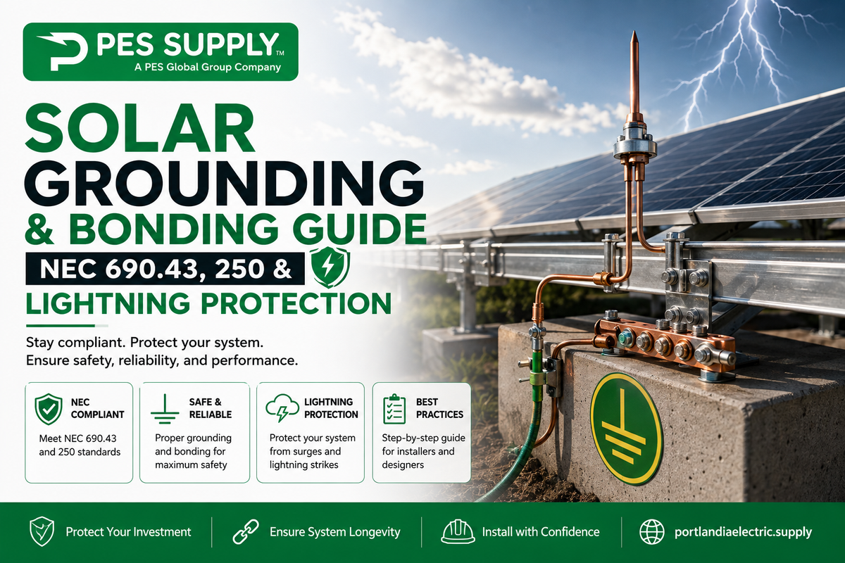
Grounding and bonding are among the most misunderstood yet critically important aspects of solar PV system installation. Proper grounding protects personnel from electrical shock, ensures that fault currents are safely cleared by overcurrent devices, minimizes fire hazards, and protects equipment from lightning-induced surges. NEC Article 690 (specifically Part V: Grounding and Bonding, sections 690.41 through 690.47) provides the PV-specific requirements, which supplement the general grounding requirements in NEC Article 250.
Additionally, NFPA 780, the Standard for the Installation of Lightning Protection Systems, provides requirements for lightning protection on structures including solar arrays. This comprehensive guide covers equipment grounding versus system bonding, NEC 690.43 requirements, grounding conductor sizing, bonding jumpers, lightning protection systems, surge protection device placement, and grounding electrode system requirements. PES Supply stocks 50,000+ SKUs from 169 authorized brands, including all the electrical accessories, disconnects, conduit, and charge controllers needed for code-compliant grounding and bonding installations. Standard delivery is 7-10 business days.
⚡ Quick Answer
PV grounding and bonding compliance rests on two distinct systems working together: equipment grounding (bonding non-current-carrying metal parts — frames, racking, enclosures — per NEC 690.43) and system bonding (referencing the DC circuit to ground, typically via functional grounding in modern transformerless inverters per NEC 690.41). Equipment grounding conductors are sized off NEC Table 250.122 based on OCPD rating; grounding electrode conductors are sized off NEC 250.66 based on the largest ungrounded service conductor. Nearly all PV DC circuits over 30V/8A require GFDI protection, and the 2023/2026 NEC now mandates UL 1449-listed "PV SPD" surge protection at DC combiners and disconnects. Dedicated lightning protection under NFPA 780 is not universally required — it's a risk-based decision driven by lightning flash density, structure exposure, and AHJ requirements.
Key Takeaways for PV Grounding and Bonding
- Grounding ≠ Bonding: grounding stabilizes voltage relative to earth; bonding creates the low-impedance fault-current path that lets OCPDs actually clear a fault. You need both.
- Equipment Grounding Is Mandatory Regardless of Voltage: NEC 690.43 requires all exposed non-current-carrying metal parts — module frames, racking, enclosures, conduit — to be grounded.
- Conductor Sizing Is Table-Driven: EGCs size off Table 250.122 by OCPD rating; GECs size off Table 250.66 by the largest ungrounded conductor — not by voltage drop or "best practice" guessing.
- Racking Bonding Must Be Listed: mounting hardware used for module-frame bonding must be UL 2703 listed and identified for the specific module and racking combination.
- GFDI Protection Is Nearly Universal: DC circuits over 30V or 8A require ground-fault detector-interrupter protection — the exception for solidly grounded, ≤2-module circuits rarely applies in practice.
- DC Surge Protection Is Now Mandatory: the 2023/2026 NEC requires UL 1449-listed "PV SPD" devices at DC combiners, power converters, or disconnects.
- PES Supply: grounding lugs, bonding jumpers, ground rods, SPDs, disconnects, and conduit in stock from 169 authorized brands with 7-10 business day delivery.
In This Guide
- 1. Equipment Grounding vs. System Bonding
- 2. NEC 690.41: DC Circuit Grounding Configurations
- 3. NEC 690.43: Equipment Grounding and Bonding Requirements
- 4. Grounding Conductor Sizing
- 5. Bonding Jumpers
- 6. Grounding Electrode System
- 7. Lightning Protection Systems (NFPA 780)
- 8. Surge Protection Device Placement
- 9. Soares Book on Grounding: Key Principles
- 10. Grounding and Bonding Inspection Checklist
- 11. Common Grounding and Bonding Mistakes
- 12. Grounding System Design Summary
- Frequently Asked Questions
EGC vs. GEC: Sizing Each Conductor from the Right NEC Table


The most expensive grounding mistake I see is also the simplest: somebody sized the equipment grounding conductor off the grounding electrode table, or vice versa. They are different conductors with different jobs and different sizing rules. The EGC (equipment grounding conductor) carries fault current back to the source so the breaker trips—NEC 250.122 sizes it off the overcurrent device protecting the circuit. The GEC (grounding electrode conductor) ties the system to earth—NEC 250.166 covers the DC side of PV systems. Use the wrong table and you have either an undersized fault path or a failed inspection, sometimes both.
The 250.122 EGC table is the one you will use weekly, so here are the rows that cover nearly every solar and electrical job we touch—copper conductors, sized from the rating of the overcurrent device ahead of the circuit:
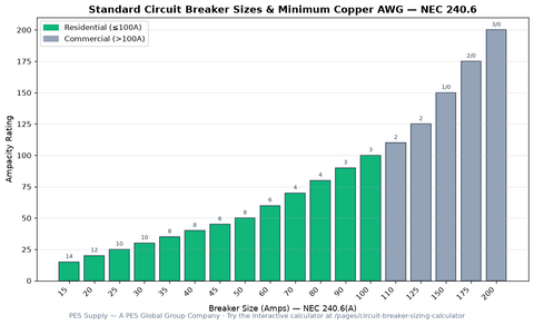
| OCPD Rating (NEC 240.6) | Min Copper EGC (NEC 250.122) | Typical Solar Application | Field Note |
|---|---|---|---|
| 15 A | 14 AWG | Small AC branch circuits | Rarely the limit on PV work — voltage drop decides first |
| 20 A | 12 AWG | Residential inverter output circuits | Match the ungrounded conductors unless upsized for VD |
| 30 A | 10 AWG | Small inverter / subpanel feeds | If you upsize the hots for voltage drop, upsize the EGC proportionally (250.122(B)) |
| 60 A | 10 AWG | Mid-size inverter AC outputs | The most common residential ESS interconnect size |
| 100 A | 8 AWG | Large residential / light commercial inverters | Check conduit fill — 3×2 AWG + 8 AWG eats a 1-inch EMT |
| 200 A | 6 AWG | Commercial service interconnections | Supply-side taps under 705.12 land here constantly |
| 400 A | 3 AWG | Large commercial services | Grounding electrode conductor sizing diverges — check 250.166/250.66 |
Read the 250.122(B) note twice: when you upsize ungrounded conductors for voltage drop—which long PV home runs demand—the EGC must be upsized by the same proportion. A 200-foot inverter run that jumps from 6 AWG to 2 AWG hots cannot keep a 10 AWG EGC. On the DC side, 250.166 ties the grounding electrode conductor to the size of the PV circuit conductors, and your AHJ will have an opinion on interpretation—ask before rough-in, not after. Our grounding and bonding reference walks the terminology, and the conductor side is covered in the ampacity chart and conduit fill chart.
A grounding electrode system handles fault currents and stabilizes voltage references. It does not, by itself, protect a building from a lightning strike—and it was never designed to. NFPA 780 is the standard for lightning protection systems, and it becomes a real conversation on three kinds of projects: tall or isolated structures (barns, ag buildings, hilltop arrays), occupancies with people who cannot evacuate quickly (schools, care facilities), and any site where the owner's insurance carrier has started asking pointed questions.
The decision logic I use with owners is straightforward. If the structure would need lightning protection without the array, adding 600 solar modules does not change the answer—but it does raise the stakes, because now a strike can find the building through the DC conductors. Air terminals, down conductors, and the bonding of the array frames into the lightning protection system all need to follow NFPA 780, and the PV grounding system and lightning protection system must be bonded together, never left as separate, isolated electrode networks. Two unbonded grounding systems at different potentials during a strike event is how equipment dies and fires start.
For everything short of a full NFPA 780 system, surge protection is the affordable middle layer: listed SPDs at the inverter DC input, at the AC service, and at any long external run. Selection and placement are covered device-by-device in our surge protection guide, and the disconnect side of the same circuits lives in the disconnect and OCPD guide.
Three grounding calls I will not forget
- The floating array. A 40 kW ground mount, three years old, kept tripping ground-fault alarms every wet spring. The racking manufacturer called for two ground rods; the installer drove one and bonded half the rails. We meggered every row, found three rail sections floating at 40+ volts to earth, bonded the lot, and the alarms died forever. Bond every rail section — not most of them.
- The $12 lug. An inspection fail on a commercial job came down to a single lay-in lug on a module frame that was never torqued. The inspector's pull test popped it off like a bottle cap. Every lug on my jobs now gets torqued to the manufacturer's spec, marked with a paint pen, and photographed for the closeout package.
- The two-rod argument. An apprentice asked why we drove a second rod instead of just upsizing the wire to a single rod. Because 25 ohms to earth (NEC 250.53) is almost never achievable with one rod in rocky soil, and the second rod is cheaper than the ground resistance tester rental to prove otherwise. Drive two, bond them, move on.
Grounding is the least glamorous part of the array and the part that decides whether a fault is a nuisance or a catastrophe. Size the EGC from 250.122, size the electrode conductors from 250.166, bond everything metal to everything else, and document it all. Hardware for the job — lugs, ground rods, clamps, and disconnects — is in the electrical collection, and the NEC compliance guide keeps the paperwork straight for inspection day.
One of the most common sources of confusion in PV system design is the distinction between equipment grounding and system bonding. Understanding the difference is essential for correct installation and inspection compliance.
1.1 Equipment Grounding
Equipment grounding (also called protective grounding or safety grounding) connects all non-current-carrying metal parts of the PV system — module frames, racking, inverter enclosures, conduit, and junction boxes — to the grounding electrode system. The purpose of equipment grounding is to:
- Provide a low-impedance path for fault currents to return to the source, enabling overcurrent protective devices to clear faults quickly.
- Limit touch voltage on metal enclosures and frames during ground fault conditions, protecting personnel from electric shock.
- Provide a reference for ground-fault detection circuits in inverters and combiner boxes.
NEC 690.43 requires that exposed non-current-carrying metal parts of PV module frames, electrical equipment, and conductor enclosures be connected to an equipment grounding conductor in accordance with NEC 250.134 or 250.136, regardless of voltage (NFPA NEC P04 First Draft).
1.2 System Bonding
System bonding (also called system grounding in older NEC editions) refers to the connection of a current-carrying conductor of the PV DC circuit to the grounding electrode system. In modern PV systems, this is typically achieved through functional grounding, where the inverter or electronic power converter provides a ground reference for the DC circuit without a solid hard-wired connection to ground. The purpose of system bonding is to:
- Stabilize the system voltage relative to ground, preventing excessive voltage buildup on DC conductors.
- Provide a reference for ground-fault detection and interruption (GFDI) circuits.
- Limit overvoltage from transients and lightning surges.
1.3 Key Terminology Table
| Term | Definition | NEC Reference |
|---|---|---|
| Equipment Grounding Conductor (EGC) | Conductor connecting non-current-carrying metal parts to the grounding electrode system. | 250.118, 690.43 |
| Grounding Electrode Conductor (GEC) | Conductor connecting the grounding electrode system to the equipment grounding system. | 250.66, 690.47 |
| System Bonding Jumper | Connection between a grounded circuit conductor and the equipment grounding conductor. | 250.28, 690.41 |
| Main Bonding Jumper | Connection at the service equipment between the grounded conductor and the equipment grounding conductor. | 250.24(B), 250.28 |
| Bonding Jumper | Conductor connecting two or more metal parts to ensure electrical continuity. | 250.30, 250.102 |
| Grounding Electrode | Conducting object (rod, plate, pipe, concrete-encased, or ground ring) in direct contact with earth. | 250.52, 690.47 |
NEC 690.41 specifies the permitted grounding configurations for PV system DC circuits. The NEC has evolved from requiring solidly grounded PV systems to permitting several functional grounding approaches that provide equivalent safety while accommodating transformerless inverter designs.
2.1 Permitted Configurations (690.41(A))
One or more of the following system configurations must be employed for PV system DC circuits:
- Functionally grounded circuits through listed equipment: The inverter or power converter provides a ground reference without a hardwired DC-to-ground connection. This is the most common configuration in modern transformerless inverters.
- Bipolar circuits: Arrays with a functional ground reference at the center tap, per NEC 690.7(C).
- Circuits not isolated from the grounded inverter output: Where the DC circuit shares a ground reference with the AC output through the inverter.
- Ungrounded circuits: Neither DC conductor is referenced to ground. Requires listed ground-fault detection equipment.
- Solidly grounded circuits: A DC conductor is directly connected to ground without impedance. Permitted as an exception in 690.41(B).
- Other equivalent methods: Circuits using equipment listed and identified for the purpose that accomplish equivalent protection per NEC 250.4(A).
2.2 Ground-Fault Detection and Interruption (690.41(B))
PV system DC circuits that exceed 30 volts or 8 amperes must be provided with DC ground-fault detector-interrupter (GFDI) protection meeting the requirements of 690.41(B)(1) and (B)(2) to reduce fire hazards. This requirement applies to virtually all residential and commercial string inverter systems.
Solidly grounded PV source circuits with not more than two modules in parallel and not on or in buildings are permitted to be installed without GFDI protection. However, this exception is rarely applicable in practice.
The GFDI system must detect ground faults in the DC circuit, interrupt the fault current, and indicate that a fault has occurred. Modern inverters typically integrate this functionality, with the inverter listed to UL 1741 for compliance (NFPA NEC 2022 P04).
⚠ Important: GEC Sizing for Separately Derived Systems
NEC 250.166 requires that grounding electrode conductors for separately derived systems (like PV inverters with isolation transformers) be sized per Table 250.66, not 250.122. An undersized GEC is a common inspection failure point.
NEC 690.43 contains the specific requirements for equipment grounding and bonding in PV systems. These requirements supplement the general provisions of Article 250 and address the unique characteristics of PV installations.
3.1 General Requirement
Exposed non-current-carrying metal parts of PV module frames, electrical equipment, and conductor enclosures must be connected to an equipment grounding conductor in accordance with NEC 250.134 or 250.136, regardless of voltage. Equipment grounding conductors and devices must comply with 690.43(A) through (E) (NFPA NEC P04 PI Submittals).
🔧 Pro Tip: Grounding Lug Selection
NEC 690.43 requires that all exposed non-current-carrying metal parts of PV system equipment be grounded. Use tin-plated copper grounding lugs with stainless steel hardware — standard zinc-plated lugs corrode within 2-3 years on rooftop installations, creating a high-resistance ground path.
3.2 PV Module Mounting Systems and Devices (690.43(A))
Devices and systems used for mounting PV modules that are also used for bonding module frames must be listed, labeled, and identified for bonding PV modules. Devices that mount adjacent PV modules are permitted to bond adjacent modules to each other. This requirement references UL 2703, the Standard for Mounting Systems, Mounting Devices, Clamping/Retention Devices, and Ground Lugs for Use with Flat-Plate Photovoltaic Modules and Panels.
The 2026 NEC clarifies that bonding devices must be listed, labeled, and identified for use with specific modules. This means that the bonding method must be compatible with the specific module manufacturer's instructions and the UL 2703 listing for the racking system (NFPA NEC P04 SD Meeting Agenda).
3.3 Equipment Secured to Grounded Metal Supports (690.43(B))
Devices listed, labeled, and identified for bonding and grounding the metal parts of PV systems are permitted to bond the metal parts of devices and equipment secured to grounded metal supports. This allows listed racking components and bonding hardware to serve as the equipment grounding path between module frames and the grounding electrode system.
3.4 Bonding Over 250 Volts (690.43(D))
The bonding requirements in NEC 250.97 apply only to solidly grounded PV system circuits operating over 250 volts to ground. For functionally grounded and ungrounded systems, the standard bonding requirements of Article 250 apply without the additional 250.97 provisions, as long as the equipment grounding path meets the impedance requirements for proper fault clearing.
3.5 Flexible Equipment Grounding Conductors for Tracking Arrays (690.43(E))
The 2026 NEC introduces expanded requirements for flexible equipment grounding and bonding conductors connected to moving parts of tracking PV arrays. Equipment grounding or bonding conductors exposed to cyclical movement must be one of the following:
- Wire-type equipment grounding conductors that meet the minimum strand count requirements in Table 690.31(C)(4).
- Flexible braided bonding straps listed and identified as suitable for the application.
- Other equipment listed and identified as suitable for the application.
This requirement ensures that the repeated flexing of tracking array movement does not cause fatigue failure of grounding conductors, which could leave the array ungrounded (NFPA NEC P04 SD Prelim SR).
Proper sizing of grounding conductors in PV systems is governed by NEC 690.45 for equipment grounding conductors, NEC 250.122 (Table 250.122) for sizing criteria, and NEC 250.66 for grounding electrode conductors.
4.1 Equipment Grounding Conductor Sizing (NEC 690.45)
Equipment grounding conductors for PV system circuits must be sized in accordance with NEC Table 250.122, based on the rating of the overcurrent protective device in the circuit. Where no OCPD is used in the circuit, an assumed OCPD rated in accordance with 690.9(B) (125% of the maximum circuit current) must be used when applying the table. Importantly, increases in equipment grounding conductor size to address voltage drop considerations are not required by the NEC, though they are considered best practice.
NEC Table 250.122: Equipment Grounding Conductor Sizes
| OCPD Rating (Amps) | Copper EGC (AWG) | Aluminum or Copper-Clad Aluminum EGC (AWG) |
|---|---|---|
| 15 | 14 | 12 |
| 20 | 12 | 10 |
| 30 | 10 | 8 |
| 40 | 10 | 8 |
| 60 | 10 | 8 |
| 100 | 8 | 6 |
| 200 | 6 | 4 |
| 300 | 4 | 2 |
| 400 | 3 | 1 |
| 500 | 2 | 1/0 |
| 600 | 1 | 2/0 |
| 800 | 1/0 | 3/0 |
| 1000 | 2/0 | 4/0 |
| 1200 | 3/0 | 250 kcmil |
| 1600 | 4/0 | 350 kcmil |
| 2000 | 250 kcmil | 400 kcmil |
4.2 Grounding Electrode Conductor Sizing (NEC 250.66)
The grounding electrode conductor (GEC) connects the equipment grounding system to the grounding electrode. NEC 250.66 specifies the minimum GEC size based on the size of the largest ungrounded service-entrance conductor or equivalent area for parallel conductors:
| Largest Ungrounded Conductor (AWG or kcmil) | Copper GEC (AWG or kcmil) | Aluminum GEC (AWG or kcmil) |
|---|---|---|
| 2 or smaller | 8 | 6 |
| 1 or 1/0 | 6 | 4 |
| 2/0 or 3/0 | 4 | 2 |
| 4/0 or 250 | 2 | 1/0 |
| Over 250 through 500 | 1/0 | 3/0 |
| Over 500 through 1000 | 2/0 | 4/0 |
| Over 1000 | 3/0 | 250 kcmil |
NEC 250.66(A) limits the maximum required GEC size for rod, pipe, or plate electrodes to 6 AWG copper. NEC 250.66(C) limits the maximum required GEC for a concrete-encased electrode to 4 AWG copper. For ground ring electrodes, the GEC must be not smaller than the ground ring conductor itself.
4.3 Grounding Conductor Sizing Examples
Example 1: Residential PV System
- Inverter AC output: 7.6 kW at 240 V = 31.7 A.
- AC breaker size: 40 A.
- From Table 250.122: EGC = 10 AWG copper.
- DC string fuse: 20 A (for each string in a 2-string system).
- From Table 250.122: String EGC = 12 AWG copper.
- Main AC EGC to grounding electrode: From Table 250.66, based on 4 AWG service conductor = 8 AWG copper.
Example 2: Commercial PV System (100 kW)
- Array-level DC OCPD: 250 A.
- From Table 250.122: Array EGC = 4 AWG copper.
- Inverter AC output breaker: 175 A at 480 V three-phase.
- From Table 250.122: AC EGC = 6 AWG copper.
- Service entrance: 4/0 AWG aluminum.
- From Table 250.66: GEC = 2 AWG copper.
Bonding jumpers ensure electrical continuity between metal parts that are mechanically connected but may not provide a reliable electrical path due to paint, corrosion, or mechanical connections. In PV systems, bonding jumpers are critical at several points:
5.1 Racking Bonding
Most PV racking systems use listed bonding hardware (per UL 2703) that bonds module frames to the racking rails and adjacent modules without requiring separate bonding jumpers. However, where racking sections are spliced or where dissimilar metals are joined, bonding jumpers may be required:
- Across racking splice joints that are not listed for bonding.
- Between separate racking sections or arrays.
- Between the racking system and the equipment grounding conductor path to the inverter.
- Between metal conduit sections that are not inherently bonded by threaded connections.
5.2 Bonding Jumper Sizing
Bonding jumpers must be sized in accordance with NEC 250.102, based on the size of the ungrounded conductors in the circuit or the OCPD rating. For equipment bonding jumpers on the line side of the service, Table 250.102(C)(1) applies. For bonding jumpers on the load side, the sizing follows Table 250.122 (same as EGC sizing).
5.3 Intersystem Bonding
NEC 250.94 requires an intersystem bonding termination (IBT) at the service equipment or at the grounding electrode system for connecting other systems including communications, CATV, and PV. The IBT must:
- Be accessible for connection and inspection.
- Have a capacity for at least three bonding conductors.
- Be listed for the purpose, or be a listed grounding electrode system connector.
- Be configured so that any bonding conductor can be disconnected without disconnecting other bonding conductors.
The bonding conductor connecting the PV system to the IBT must be copper or other corrosion-resistant material, not smaller than 14 AWG, and have an ampacity not less than the circuit conductors (NFPA NEC P05 First Draft).
NEC 690.47 specifies how PV systems must be connected to the building's grounding electrode system. The requirements vary depending on whether the PV system is AC-coupled or DC-coupled, and whether the inverter is located at the array or remotely.
6.1 NEC 690.47 Requirements
PV array equipment grounding conductors must be connected to a grounding electrode system in accordance with Part VII of Article 250. This connection must be in addition to any other equipment grounding conductor requirements in 690.43(C). The PV array equipment grounding conductors must be sized in accordance with 690.45.
For solidly grounded PV system DC circuits, the grounding connection must be made from any single point on the PV DC system to a point in the grounding electrode system per 690.47(A) (NFPA NEC P04 First Draft).
6.2 Grounding Electrode Types (NEC 250.52)
The permitted grounding electrodes include:
| Electrode Type | NEC Reference | Minimum Specification |
|---|---|---|
| Metal Underground Water Pipe | 250.52(A)(1) | 10 ft contact, supplemented by a supplemental electrode |
| Concrete-Encased Electrode (Ufer) | 250.52(A)(3) | ½-inch rebar, 20 ft minimum, encased in concrete |
| Ground Ring | 250.52(A)(4) | #2 AWG copper minimum, 2.5 ft depth, encircling building |
| Rod and Pipe Electrode | 250.52(A)(5) | ½-inch diameter pipe or 5/8-inch rod, 8 ft depth |
| Plate Electrode | 250.52(A)(6) | 2 sq ft surface area, buried 2.5 ft below grade |
| Other Listed Electrodes | 250.52(A)(7) | Listed for grounding, per manufacturer instructions |
All grounding electrodes present at each building or structure must be bonded together to form the grounding electrode system per NEC 250.50. If none of the electrodes in 250.52(A)(1) through (A)(7) exist, one or more must be installed.
6.3 Supplemental Electrode Requirements
Where a rod, pipe, or plate electrode is used as the sole grounding electrode and the resistance to ground exceeds 25 ohms, a supplemental electrode must be installed. The supplemental electrode must be bonded to the first electrode and may be installed at any distance. In practice, many jurisdictions require the installation of two ground rods spaced at least 6 feet apart regardless of measured resistance, as a conservative approach to achieving adequate grounding.
6.4 Large-Scale PV Grounding
For large-scale PV electric supply stations (rated 5,000 kW or greater, governed by NEC Article 691), the grounding electrode system details must be included in the project documentation per NEC 691.6. The informational note references IEEE 2778-2020, Guide for Solar Power Plant Grounding for Personnel Protection. Grounding and bonding connections between the grounding electrode system and PV module frames must comply with the design documentation. Fence bonding and grounding requirements must also be detailed in the documentation (NFPA NEC P04 SD Prelim SR).
Bonding conductors for large-scale systems must be solid copper, insulated or bare, and not smaller than 8 AWG. Connections must be made by exothermic welding or by listed pressure connectors or clamps of stainless steel, brass, copper, or copper alloy.
Lightning poses a significant risk to PV systems, particularly ground-mount arrays in open areas and rooftop systems on tall buildings. While NEC Article 690 addresses grounding and bonding for normal electrical safety, NFPA 780, the Standard for the Installation of Lightning Protection Systems, provides the comprehensive requirements for dedicated lightning protection.
7.1 NFPA 780 Scope
NFPA 780 provides requirements for traditional lightning protection system installations on ordinary structures, miscellaneous structures, heavy-duty stacks, structures containing flammable materials, wind turbines, watercraft, airfield lighting circuits, and solar arrays (NFPA 780 Blog). The purpose of NFPA 780 is to safeguard persons and property from hazards arising from exposure to lightning.
7.2 Key NFPA 780 Requirements for Solar Arrays
While NFPA 780 is a comprehensive document covering all types of structures, several provisions are particularly relevant to solar installations:
- Air terminals (lightning rods): Must be listed or labeled for the purpose and installed to intercept lightning strikes before they reach the PV array or building structure.
- Down conductors: Must provide a low-impedance path from air terminals to the grounding electrode system. Conductor bends must be no less than 90 degrees with a minimum 8-inch bending radius.
- Listed components: All lightning conductors, air terminals, and other components must be listed or labeled for the purpose, with installation following manufacturer instructions.
- Workmanlike installation: All lightning protection system installations must be done in a neat and workmanlike manner, consistent with NEC requirements.
- Installer qualifications: Installers must have the skills needed, often through proven experience and certifications accepted by the AHJ.
- Maintenance: Installers must provide maintenance guidelines to the owner upon completion, and periodic inspections must be performed as determined by the AHJ.
NFPA 780 is available as a published standard from the NFPA (NFPA 780 Product Page). Ground ring electrodes for lightning protection systems must be bare copper or 40% copper-clad steel (CCS) conductors meeting or exceeding 115,000 circular mils. Bonding conductors for lightning protection must have a cross-sectional area of at least 17,800 circular mils (approximately #6 AWG copper) (NFPA 780 SD PC Responses).
7.3 Separation Distance
NFPA 780 specifies a minimum separation distance between lightning protection system conductors and the grounded metal body of the structure being protected. This separation prevents side-flash, where lightning arcs from the down conductor to nearby metal objects. The required separation distance depends on the conductor length, the grounding resistance, and the voltage of the lightning surge.
7.4 When Lightning Protection Is Required
Neither the NEC nor NFPA 780 mandates lightning protection for all PV installations. The decision to install a dedicated lightning protection system should be based on a risk assessment considering:
- Lightning flash density (strikes per square kilometer per year) for the geographic location.
- Building height and exposure (isolated structures are at higher risk).
- Soil resistivity and the effectiveness of the existing grounding system.
- Value of equipment and consequences of downtime.
- Insurance requirements or AHJ mandates.
In areas with high lightning frequency (such as Florida, the Gulf Coast, and the central United States), lightning protection is strongly recommended for ground-mount arrays and rooftop systems on commercial buildings.
Surge protective devices (SPDs) are essential for protecting PV system electronics from transient overvoltages caused by lightning, utility switching, and other sources. The NEC has progressively strengthened SPD requirements in recent editions.
8.1 DC Surge Protection Requirements
The 2023 NEC and 2026 NEC require that PV system DC circuits have SPDs marked as "PV SPD" installed at the DC combiners, electronic power converters, or DC PV system disconnecting means. These SPDs must be listed to UL 1449, the Standard for Surge Protective Devices. Electric power production and distribution network equipment supplied by a PV system must also be provided with an SPD (NFPA NEC P04 PI Submittals).
8.2 AC Surge Protection
While the NEC mandates DC-side SPDs for PV systems, AC-side surge protection is also recommended at:
- The inverter AC output circuit.
- The main service panel or point of interconnection.
- Subpanels feeding critical loads (in battery-backed systems).
- Communications and monitoring circuits.
8.3 SPD Selection and Sizing
| SPD Location | UL Standard | Type | Minimum Voltage Rating | Minimum I-n Rating |
|---|---|---|---|---|
| DC Combiner / Array | UL 1449 (PV SPD) | Type 1 or Type 2 | System Vmax × 1.15 | 10 kA |
| Inverter DC Input | UL 1449 (PV SPD) | Type 1 or Type 2 | System Vmax × 1.15 | 10 kA |
| Inverter AC Output | UL 1449 | Type 1 or Type 2 | System Vac | 20 kA |
| Main Service Panel | UL 1449 | Type 1 or Type 2 | System Vac | 40–80 kA |
| Subpanel (critical loads) | UL 1449 | Type 2 | System Vac | 20–40 kA |
The SPD voltage rating must exceed the system's maximum operating voltage with adequate margin (typically 115% of the maximum system voltage). The nominal discharge current (I-n) rating should be selected based on the expected surge environment, with higher values recommended for installations in high-lightning-risk areas.
8.4 SPD Installation Best Practices
- Minimize lead length: SPD lead length directly affects clamping voltage. Keep leads as short and straight as possible, ideally under 12 inches total.
- Install at the point of entry: Place DC SPDs as close as possible to the DC combiner or disconnect, and AC SPDs near the service panel or interconnection point.
- Bond to the EGC: Connect the SPD grounding terminal to the equipment grounding conductor with the shortest practical path.
- Use Type 1 SPDs for line-side: Type 1 SPDs can be installed on the line side of the main disconnect and do not require an external OCPD. Type 2 SPDs require an OCPD and are installed on the load side.
- Consider cascading: In high-risk areas, install SPDs at multiple points (DC combiner, inverter, AC panel) for layered protection.
- Replace after events: SPDs have a finite service life. After a significant lightning event or when the indicator shows failure, replace the SPD.
The Soares Book on Grounding, published by the IAEI (International Association of Electrical Inspectors), is the authoritative reference for NEC grounding and bonding interpretation. Several key principles from this resource are particularly relevant to PV system grounding:
- The EGC must provide an effective ground-fault current path: The equipment grounding conductor must be sized and installed to carry fault current long enough for the OCPD to clear the fault. Low impedance is more important than conductor size alone.
- Bonding creates the fault path: All metal parts that could become energized during a fault must be bonded to the equipment grounding system. Unbonded metal parts are a shock hazard.
- Separate grounding electrodes must be bonded: If a PV array has its own ground rod and the building has a separate grounding electrode, they must be bonded together to prevent differences in ground potential that could cause touch voltage hazards or circulating currents.
- Grounding does not clear faults; bonding does: The grounding electrode connection stabilizes voltage but does not provide a fault path. The equipment grounding conductor and bonding network provide the low-impedance path that enables OCPD operation.
- Neutral-current on grounding conductors is prohibited: No connection shall be made to grounding and bonding conductors that results in that conductor carrying current under normal conditions, unless permitted by specific code provisions (NFPA NEC P05 FD PI Responses).
Use this checklist during pre-inspection verification to ensure grounding and bonding compliance:
10.1 Array Grounding
- [ ] Module frames bonded to racking using UL 2703 listed bonding devices.
- [ ] Racking bonded across all splice joints and between sections.
- [ ] Equipment grounding conductor from array to inverter/combiner sized per Table 250.122.
- [ ] EGC continuous from array through all disconnects to grounding electrode system.
- [ ] Ground lugs torqued to manufacturer specifications.
- [ ] No dissimilar metal connections without listed bonding devices (galvanic corrosion prevention).
- [ ] Tracking array grounding conductors meet flexibility requirements (Table 690.31(C)(4) or braided straps).
10.2 Inverter and Equipment Grounding
- [ ] Inverter enclosure grounded per manufacturer instructions.
- [ ] All metal enclosures, junction boxes, and conduit bonded to EGC.
- [ ] GFDI protection functional and tested (NEC 690.41(B)).
- [ ] Combiner box equipment grounding busbar bonded to enclosure.
- [ ] DC SPD marked "PV SPD" installed at combiner or DC disconnect (UL 1449 listed).
10.3 Grounding Electrode System
- [ ] Grounding electrode(s) installed per NEC 250.52 requirements.
- [ ] Grounding electrode conductor sized per NEC 250.66.
- [ ] GEC connections accessible and properly made (exothermic weld or listed clamp).
- [ ] All grounding electrodes at the building bonded together (NEC 250.50).
- [ ] Intersystem bonding termination provided at service (NEC 250.94).
- [ ] Ground resistance test performed (target ≤ 25 ohms for rod/pipe/plate electrodes).
10.4 AC Side Grounding
- [ ] Main bonding jumper installed at service equipment (NEC 250.24(B)).
- [ ] AC EGC from inverter to main panel sized per Table 250.122.
- [ ] Neutral conductor isolated from ground at subpanels and inverter (except at main service).
- [ ] AC SPD installed at main service panel (Type 1 or Type 2, UL 1449).
| Mistake | Consequence | Correct Practice |
|---|---|---|
| Unbonded separate ground rods | Differences in ground potential cause touch voltage hazards and equipment damage. | Bond all grounding electrodes together with appropriately sized conductor. |
| Using racking hardware not listed for bonding | No reliable electrical continuity; frames may be ungrounded. | Use UL 2703 listed racking and bonding devices per manufacturer instructions. |
| Undersized equipment grounding conductor | Fault current may not clear OCPD in time; fire and shock risk. | Size EGC per NEC Table 250.122 based on OCPD rating. |
| Neutral-ground bond at subpanel or inverter | Parallel neutral current paths on EGC; equipment overheating. | Keep neutral isolated from ground except at main service bonding point. |
| Missing DC surge protection | Inverter and electronics vulnerable to lightning and transient damage. | Install UL 1449 listed PV SPDs at DC combiners and disconnecting means. |
| Loose or corroded ground connections | High-impedance ground path; faults may not clear; touch voltage risk. | Torque all connections to spec; use listed connectors; protect from corrosion. |
| GEC not sized for largest conductor | Insufficient capacity to carry surge or fault current to ground. | Size GEC per NEC 250.66 based on largest ungrounded conductor. |
| No intersystem bonding termination | Communication and PV systems at different ground potentials; equipment damage. | Install IBT at service per NEC 250.94. |
The following table summarizes the key grounding conductor sizes for common PV system configurations:
| System Size | DC String EGC (Cu) | Array EGC (Cu) | AC EGC (Cu) | GEC (Cu) | Lightning Protection Bonding (Cu) |
|---|---|---|---|---|---|
| Residential (5–10 kW) | 12 AWG | 10 AWG | 10 AWG | 8 AWG | 6 AWG (if applicable) |
| Residential + Storage (10–15 kW) | 12 AWG | 8 AWG | 8 AWG | 6 AWG | 6 AWG (if applicable) |
| Commercial (30–100 kW) | 10 AWG | 6 AWG | 6 AWG | 4 AWG | 2 AWG |
| Commercial (100–500 kW) | 10 AWG | 4 AWG | 4 AWG | 2 AWG | 1/0 AWG |
| Utility-scale (500 kW+) | 8 AWG | 2/0 AWG | 2/0 AWG | 1/0 AWG | 2/0 AWG |
Sizes shown are minimums based on typical OCPD ratings. Always verify actual sizes against the specific system design, OCPD ratings, and local code requirements. Browse our electrical accessories for grounding lugs, bonding jumpers, ground rods, and SPDs.
Proper grounding and bonding are essential for the safety, performance, and longevity of solar PV systems. NEC Article 690 (Part V: Grounding and Bonding) provides PV-specific requirements that supplement the general provisions of Article 250, addressing the unique characteristics of PV power sources including functional grounding, module frame bonding, and DC ground-fault protection. NFPA 780 provides additional requirements for dedicated lightning protection systems that may be needed in high-risk areas. By understanding the distinctions between equipment grounding and system bonding, properly sizing grounding and bonding conductors, installing surge protection devices at the required locations, and maintaining an effective grounding electrode system, installers can ensure that their PV installations protect personnel, equipment, and property for the full system life.
Frequently Asked Questions
What is NEC 690.43 and why does it matter?
NEC 690.43 requires that all exposed non-current-carrying metal parts of PV equipment be grounded to the equipment grounding conductor. This includes module frames, racking rails, inverter enclosures, and junction boxes. Failure to properly ground can result in lethal shock hazards and fire risks.
Do I need a separate grounding electrode for my PV system?
NEC 690.47 requires that PV systems be bonded to the existing building grounding electrode system. A separate electrode is not typically required unless the PV array is more than 50 feet from the main service — in that case, a supplemental grounding electrode (ground rod) is required at the array location.
What is the difference between grounding and bonding?
Grounding connects electrical systems to earth (via grounding electrodes). Bonding connects metal parts together to create a continuous low-impedance path for fault currents. Both are required — grounding without bonding does not provide protection, and bonding without grounding does not dissipate fault energy to earth.
Does my solar array need lightning protection?
Not automatically. NFPA 780 lightning protection is typically warranted for tall or isolated structures, critical occupancies, or where insurers require it. Every array, however, needs the fundamentals: a proper grounding electrode system, all metal bonded together, and listed surge protection devices at the inverter and service. If a lightning protection system exists on the building, the PV grounding system must be bonded to it — never left as a separate, isolated network.
How often should grounding connections be inspected?
At commissioning, at the first annual O&M visit, and every year after. Field checks should include torque verification on a sample of bonding lugs, visual inspection of weep-prone connectors and below-grade clamps for corrosion, and continuity testing across rail splices and module frames. Document every reading — a grounding system that is not measured is a grounding system you are guessing about.
Ready to build your system? PES Supply stocks 50,000+ SKUs from 169 authorized brands, with delivery in 7-10 business days. Here are the products mentioned in this article:
- BR Solar Group BR-M310W
- Conext Insight Home
- DU221RB Safety Disconnect
- BR Solar Group BR-M315W
- Conext XW Conduit Box
Browse all electrical · Browse all circuit breakers · Browse all surge protection
Ready to Build a Code-Compliant Grounding System?
PES Supply provides contractors with 50,000+ SKUs from 169 authorized brands, with standard delivery in 7-10 business days. Browse our complete inventory of electrical accessories, disconnects, conduit, inverters, charge controllers, battery storage, and solar panels.
Shop Electrical Accessories Shop DisconnectsRelated Articles
About PES Supply
PES Supply is a nationwide distributor of Tier 1 solar panels, commercial inverters, battery storage systems, EV charging hardware, racking, switchgear, circuit breakers, generators, and complete electrical project kits. With 12+ distribution hubs, 50,000+ in-stock SKUs from 169 authorized brands, in-house design support, and a network of 8,500+ solution providers, PES Supply serves contractors, EPCs, developers, and businesses with fast delivery, wholesale pricing, and expert procurement guidance.
Location: 1507 Portland Ave, Louisville, KY, United States | Phone: 1 888-876-0007 | Website: www.portlandiaelectric.supply
Article: Solar Grounding and Bonding Guide: NEC 690.43, 250, and Lightning Protection
Category: Electrical Code | Grounding & Bonding | NEC Compliance
Last Updated: August 2026
Disclaimer: Code references, sizing tables, and requirements cited in this guide reflect the NEC and NFPA 780 as of August 2026, including proposed 2026 NEC changes still in the public input/comment process. Always verify current code adoption in your jurisdiction and confirm requirements with your local AHJ before finalizing a design.