Solar Disconnect and Overcurrent Protection Guide: NEC 690 Requirements Explained
Reading time: ~16 min read
Disconnects and overcurrent protection devices (OCPDs) are the safety backbone of every solar PV system. These components protect conductors, equipment, and personnel from fault currents, enable safe maintenance and emergency response, and provide the means to isolate the PV system from the grid and other power sources. NEC Article 690 contains the specific requirements for disconnecting means and overcurrent protection in PV systems, supplementing the general requirements in NEC Articles 240 and 705. This guide explains the NEC 690 requirements for DC and AC disconnects, overcurrent protection, breaker sizing, fuse selection, combiner box requirements, rapid shutdown integration, and labeling.
PES Supply stocks 50,000+ SKUs from 169 authorized brands, including a full range of disconnects, electrical accessories, conduit, and charge controllers for code-compliant solar installations. Standard delivery is 7-10 business days.
Tables of rules are fine. A worked job is better. Here is the exact OCPD calculation chain we ran last month on a 12-string commercial rooftop—500 W-class modules, 13.6 A string Isc, 1500 V system, strings landing in a rooftop combiner with a single home run to the inverter. Every step cites its code section, because the plan reviewer will check every one:
| Step | Calculation | Code Basis | Result |
|---|---|---|---|
| 1. String max current | 13.6 A × 1.25 (irradiance) | NEC 690.8(A) | 17.0 A |
| 2. Continuous duty | 17.0 A × 1.25 | NEC 690.8(B) | 21.2 A minimum conductor & OCPD basis |
| 3. String fuse | Round up to standard size | NEC 240.6, 690.9 | 25 A DC-rated PV fuse per string |
| 4. String conductor | ≥ 21.2 A @ 90°C Cu | NEC 310.16 | 12 AWG (30 A) — 10 AWG chosen for voltage drop |
| 5. Combiner output current | 12 × 13.6 A × 1.25 | NEC 690.8(A)(2) | 204 A |
| 6. Output conductor | ≥ 204 A @ 75°C Cu | NEC 310.16 | 4/0 AWG (230 A) |
| 7. Output OCPD | Next standard ≥ 204 A, ≤ conductor | NEC 240.6, 240.4(B) | 225 A DC-rated breaker |
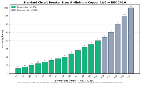
Three traps hide in this chain. First, the string fuse must be listed for DC PV service (UL 2579)—an AC fuse in a DC string circuit is a fire with a label on it. Second, the 4/0 home run's 230 A ampacity has to survive temperature derating on a hot roof; if the rooftop ambient correction pulls it under 225 A, the breaker drops or the wire grows. Third, every one of these devices needs a disconnecting means within the rules of 690.13 and 690.15—the fuse does not count as the disconnect. Cross-check the breaker side against the standard breaker sizes chart and the conductor side against the NEC ampacity chart before the submittal goes in.
For hardware, we stock DC-rated disconnects like the MidNite Solar MNEPV50 breaker for string and combiner circuits and the DU221RB 30 A safety disconnect for AC-side service points—both in the electrical collection.
Half the red tags I see on disconnects are location problems, not hardware problems. The device was fine; it was just on the wrong wall. This is the placement summary I hand to new project managers:
| Device | Code Section | Required Location | Field Trap to Avoid |
|---|---|---|---|
| PV system disconnect | NEC 690.13 | Readily accessible, outside or immediately inside the building entry point | Mounting it behind a locked fence gate with no signage |
| Equipment disconnect (inverter) | NEC 690.15 | Within sight of the inverter, or lockable in the open position | "Within sight" fails if you cannot see the inverter from the handle |
| AC disconnect | NEC 690.15 / utility rules | At or within sight of the meter per most utility requirements | Assuming the main breaker satisfies the utility — many require a visible-blade switch |
| Rapid shutdown initiator | NEC 690.12(C) | Readily accessible, labeled, at the service or first-responder location | Burying the initiator inside the inverter interface where a firefighter will never find it |
| Combiner fuses | NEC 690.9 | In a listed combiner, grouped and accessible for service | String fuses scattered in module-level J-boxes where maintenance can't reach them |
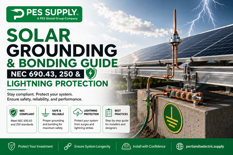
Walk the site with this table during design, not during the pre-inspection panic. And remember that every disconnect is also a bonding point—the enclosure, the raceway, and the equipment grounding conductor all tie together per the rules in our grounding and bonding guide.
Three calls that shaped how we install
- The welded fuse holder. A service call on a five-year-old ground mount: a tech had pulled a string fuse under full afternoon load with a cheap non-load-break holder. The arc welded the fuse into the clip and scorched the combiner. Now our crews open the DC disconnect first, verify zero current with the clamp meter, and only then touch a fuse. Load-break rated or nothing.
- The wrong-wall disconnect. We failed a final inspection because the AC disconnect sat around the corner from the meter—twelve feet, out of the inspector's line of sight. The utility rule said "at the meter." A $95 relocation and a re-inspection fee taught us to photograph the meter wall at the site survey and mount to the photo.
- The unlabeled initiator. A school project, perfect hardware, failed final: the rapid shutdown initiation device had no placard. The label printer now lives in the lead installer's bag, and 690.56 labeling is a line item on the commissioning checklist with a checkbox and initials.
Disconnects and OCPDs are cheap insurance installed correctly and six-figure liabilities installed casually. Size them with the worked math above, place them with the cheat sheet, torque every lug to NEC 110.14(D) specs, and document the whole chain. The NEC compliance guide and the conduit fill chart cover the rest of the inspection-day package.
NEC 690.13 establishes the requirements for the PV system disconnecting means — the primary means to disconnect the PV system from all other wiring systems, including power systems, energy storage systems, and premises wiring. The PV system disconnecting means must be installed in accordance with NEC 705.20, which governs the interconnection of power production sources ([NFPA NEC P04 Second Draft](https://docinfofiles.nfpa.org/files/AboutTheCodes/70/70_A2025_NEC_P04_SD_PCSubmittals.pdf)).
1.1 Type of Disconnect (690.13(A))
The PV system disconnecting means must simultaneously disconnect all PV system conductors that are not solidly grounded from all conductors of other wiring systems. Acceptable disconnect types include:
- A manually operable switch or circuit breaker.
- A pull-out switch with the required interrupting rating.
- A remote-controlled switch or circuit breaker that is operable locally and opens automatically when control power is interrupted.
- A device listed or approved for the intended application.
An informational note cautions that circuit breakers marked "line" and "load" may not be suitable for backfeed or reverse current applications. When using a circuit breaker as a PV disconnect in a backfed configuration, verify that the breaker is listed for backfeed use ([NFPA NEC P04 First Draft](https://docinfofiles.nfpa.org/files/AboutTheCodes/70/70_A2025_NEC_P04_FD_PIResponses.pdf)).
1.2 Lockable Open (690.13(B))
The PV system disconnecting means — or its remote operating device, or the enclosure providing access to the disconnecting means — must be lockable in the open (off) position in accordance with NEC 110.25. This requirement ensures that maintenance personnel can secure the disconnect in the off position to prevent accidental re-energization during service.
1.3 Marking (690.13(C))
Each PV system disconnecting means must be permanently marked "PV SYSTEM DISCONNECT" or equivalent. This marking must be clearly visible and legible, and must identify the disconnect as serving the PV system specifically. Additional information required on or near the disconnect includes:
- Rated maximum PV power-source short-circuit current.
- Rated maximum PV voltage.
- Maximum circuit current.
1.4 Maximum Number of Disconnects (690.13(D))
Each PV system disconnecting means must consist of not more than six switches or six sets of circuit breakers, or a combination of not more than six switches and sets of circuit breakers, mounted in a single enclosure or in a group of separate enclosures. A single PV system disconnecting means is permitted for the combined AC output of one or more inverters or AC modules.
This "six-disconnect rule" ensures that the entire PV system can be de-energized by operating a limited number of devices, facilitating emergency response. The requirement does not limit the number of PV systems that may be connected to a service.
1.5 Location and Accessibility
The PV system disconnecting means must be installed at a readily accessible location. For circuits operating above 30 volts where the disconnect is readily accessible to unqualified persons, enclosure doors or hinged covers that expose energized parts when open must be locked or require a tool to be opened. The disconnect must not be installed in bathrooms.
In addition to the PV system disconnect, NEC 690.15 requires equipment disconnecting means for isolating individual PV system components such as inverters, DC-to-DC converters, and charge controllers. The equipment disconnect must:
- Be rated for the maximum circuit current, available fault current, and voltage available at the terminals.
- Simultaneously disconnect all current-carrying conductors that are not solidly grounded.
- Be externally operable without exposing the operator to energized parts.
- Plainly indicate whether in the open (off) or closed (on) position.
- Where not within sight and within 10 feet (3 m) of the equipment, have a lockable disconnect or remote operating device per NEC 110.25.
2.1 Isolating Devices (690.15(C))
Where equipment disconnecting means are not required to be load-break rated, isolating devices may be used. Isolating devices are not intended to be operated under load and must be interlocked with a load-break disconnect to prevent opening under load. These devices are commonly used in DC combiner boxes and at module-level power electronics to provide isolation for maintenance.
NEC 690.9 governs overcurrent protection for PV system DC circuits and inverter output conductors. The requirements are structured to account for the unique current-limited nature of PV sources, which differ significantly from conventional AC power sources.
3.1 Circuits Where OCPD Is Not Required (690.9(A)(1))
Overcurrent protective devices are not required where both of the following conditions are met:
- The conductors have sufficient ampacity for the maximum circuit current (as calculated in NEC 690.8(A)).
- The currents from all sources do not exceed the maximum OCPD rating specified for the PV module or electronic power converter.
This exception applies to many simple residential string inverter systems where a single PV string feeds an inverter. Since the PV source is current-limited and the inverter cannot backfeed the array (in most configurations), the conductor ampacity inherently exceeds the available fault current, and no OCPD is needed on the DC side.
3.2 Circuits Where OCPD Is Required on One End (690.9(A)(2))
Where a circuit conductor is connected at one end to a current-limited supply (the PV array) and at the other end to a higher current source (such as parallel-connected PV strings, energy storage systems, or the utility service), overcurrent protection must be installed at the point of connection to the higher current source. This prevents the higher current source from feeding excessive current into the conductor and PV modules during a fault.
3.3 Other Circuits (690.9(A)(3))
Circuits that do not qualify for exemptions under 690.9(A)(1) or (A)(2) must be protected with one of the following methods:
- An OCPD on each end of the circuit conductor.
- An OCPD at the supply end only, where the conductor ampacity is not less than the OCPD rating after all derating, and there is no source of backfeed current.
- Electronic devices listed to prevent backfeed current in PV system DC circuits.
3.4 OCPD Rating (690.9(B))
Overcurrent protective devices for PV system DC circuits must be rated at not less than 125% of the maximum currents calculated in NEC 690.8(A). The OCPD rating is permitted to be rounded up to the next higher standard size in accordance with NEC 240.4(B). However, the conductor ampacity must still not be less than the OCPD rating after applying all correction and adjustment factors.
OCPD Sizing Calculation Example
For a PV string with Isc = 10.5 A:
- Maximum current = 10.5 × 1.25 = 13.13 A (NEC 690.8(A)).
- OCPD rating = 13.13 × 1.25 = 16.4 A, round up to next standard size = 20 A.
- Conductor ampacity must be ≥ 20 A after all derating.
3.5 PV System DC Circuit Protection (690.9(C))
A single OCPD is permitted to protect the PV modules, DC-to-DC converters, and conductors of each circuit. Where a single OCPD protects multiple parallel-connected PV string circuits, the ampacity of each conductor must not be less than:
- The rating of the OCPD, plus
- The sum of the maximum currents (from 690.8(A)(1)(a)) for the other parallel-connected PV string circuits protected by the OCPD.
All OCPDs used to protect circuits must be placed in the same polarity for all circuits within a PV system. The devices must be accessible but are not required to be readily accessible.
3.6 Marking (690.9(D))
OCPDs used in PV system DC circuits must be marked "Photovoltaic" or "PV." This marking distinguishes DC PV-rated fuses and breakers from standard AC devices, preventing incorrect substitution during maintenance or replacement.
The DC disconnect serves as the primary means to isolate the PV array from the inverter and the rest of the system. While NEC 690.13 provides the general requirements for PV system disconnecting means, additional considerations apply to DC disconnects specifically.
4.1 DC Disconnect Ratings
DC disconnects must be rated for:
- Voltage: The maximum PV system DC voltage, as calculated per NEC 690.7 (cold-temperature corrected Voc).
- Current: The maximum circuit current as calculated per NEC 690.8(A).
- Interrupting rating: The available fault current at the disconnect terminals. For PV source circuits, the available fault current is typically limited to the sum of parallel string Isc values, but where battery storage or utility backfeed is present, higher interrupting ratings may be required.
| System Size | Typical DC Voltage | Typical DC Current | Recommended DC Disconnect Rating |
|---|---|---|---|
| Residential (5–10 kW) | 300–600 V DC | 10–30 A | 600 V, 30–60 A, 10 kAIC |
| Residential with storage | 48–600 V DC | 50–200 A | 600 V, 100–250 A, 20 kAIC |
| Commercial (50–250 kW) | 600–1000 V DC | 100–400 A | 1000 V, 200–600 A, 20 kAIC |
| Utility-scale (500 kW+) | 1000–1500 V DC | 300–1000 A | 1500 V, 400–1200 A, 30 kAIC |
4.2 DC Disconnect Placement
The DC disconnect should be located as close as practical to the inverter to minimize the length of energized DC conductors inside the building. NEC 690.31(E) requires that PV system DC circuits exceeding 30 volts or 8 amperes that are inside buildings be contained in metal raceways, MC cable, or metal enclosures from the point of penetration to the DC disconnect. This ensures that energized DC conductors within the building are physically protected.
The AC disconnect isolates the inverter's AC output from the building's electrical system and the utility grid. Requirements for AC disconnect placement include:
5.1 Utility-Accessible AC Disconnect
Many utilities require an external, lockable AC disconnect in a readily accessible location for use by utility personnel during emergency response or maintenance. While the NEC does not always mandate a separate utility-accessible AC disconnect (the main service breaker may suffice), utility interconnection requirements often do. Always verify utility interconnection requirements during the permitting process.
5.2 Inverter AC Disconnect
Many modern string inverters include an integrated AC disconnect, eliminating the need for a separate external AC disconnect between the inverter and the point of interconnection. However, where the inverter is not within sight of the point of interconnection, a separate AC disconnect may be required per NEC 705.20 to provide local isolation.
5.3 AC Disconnect Rating
The AC disconnect must be rated for:
- The inverter's maximum AC output current.
- The system AC voltage (120/240 V single-phase for residential; 208 V or 480 V three-phase for commercial).
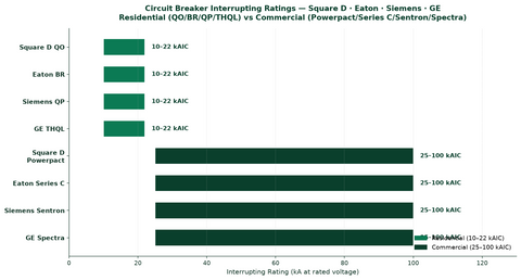
- The available fault current at the point of interconnection (typically 10,000–22,000 AIC for residential; 25,000–65,000 AIC for commercial).
Properly sizing circuit breakers for PV systems requires understanding the difference between DC-rated and AC-rated breakers, as well as the NEC requirements for continuous loads.
6.1 AC Interconnection Breaker Sizing
The AC interconnection breaker (the breaker in the main service panel that connects the inverter output to the building's electrical system) must be sized at 125% of the inverter's rated AC output current, as PV circuits are considered continuous loads:
Breaker Size = Inverter Rated AC Output Current × 1.25
| Inverter AC Output | Continuous Current (A) | 125% Rating (A) | Standard Breaker Size (A) |
|---|---|---|---|
| 3.0 kW @ 240V | 12.5 | 15.6 | 20 |
| 5.0 kW @ 240V | 20.8 | 26.0 | 30 |
| 7.6 kW @ 240V | 31.7 | 39.6 | 40 |
| 10.0 kW @ 240V | 41.7 | 52.1 | 60 |
| 15.0 kW @ 240V | 62.5 | 78.1 | 80 |
| 30.0 kW @ 480V (3φ) | 36.1 | 45.1 | 50 |
| 100.0 kW @ 480V (3φ) | 120.3 | 150.4 | 175 |
6.2 Busbar and Conductor Protection (NEC 705.12)
When connecting a PV system to a load-side breaker in an existing service panel, the NEC limits the aggregate current to protect the panel busbar:
- 120% Rule (NEC 705.12(B)(2)(3)(b)): The sum of the ratings of all overcurrent devices supplying panelboard busbars (main breaker + PV breaker) must not exceed 120% of the busbar rating.
- Formula: Main Breaker + PV Breaker ≤ 1.20 × Busbar Rating
- Example: A 200 A panel with a 200 A main breaker: 200 + PV Breaker ≤ 1.20 × 200 = 240. Maximum PV breaker = 240 − 200 = 40 A.
Alternatively, supply-side connections (before the main breaker) are permitted per NEC 705.12(A), which allows the PV interconnection ahead of the service disconnecting means. This method avoids the 120% busbar limitation but requires additional equipment and coordination with the utility.
Fuses are the primary overcurrent protection device for PV DC circuits, particularly in combiner boxes and string-level protection. PV-rated fuses differ from standard AC fuses in several important ways.
7.1 PV Fuse Characteristics
- Standard: UL 2579 (formerly UL 248-19), Standard for Photovoltaic Fuses.
- Voltage rating: 600 V, 1000 V, or 1500 V DC.
- Current rating: Typically 1–30 A for string-level protection; up to 400 A for array-level protection.
- Interrupting rating: Minimum 10 kA DC; higher ratings available for commercial systems.
- Time-current characteristics: Designed to withstand the cyclic current profile of PV circuits without nuisance tripping, while clearing fault currents quickly enough to protect conductors and modules.
- Marking: Must be marked "PV" or "Photovoltaic" per NEC 690.9(D).
7.2 Fuse Sizing Table
| Module Isc (A) | Max Current (Isc × 1.25) | OCPD Rating (× 1.25, rounded up) | Recommended Fuse | Minimum Conductor Size |
|---|---|---|---|---|
| 5.0 | 6.25 | 10 | 10 A PV fuse | 14 AWG |
| 8.0 | 10.0 | 15 | 15 A PV fuse | 12 AWG |
| 10.5 | 13.1 | 20 | 20 A PV fuse | 10 AWG |
| 12.0 | 15.0 | 20 | 20 A PV fuse | 10 AWG |
| 14.0 | 17.5 | 25 | 25 A PV fuse | 8 AWG |
| 16.0 | 20.0 | 25 | 25 A PV fuse | 8 AWG |
| 20.0 | 25.0 | 35 | 35 A PV fuse | 6 AWG |
The minimum conductor sizes in the table above assume 90°C insulation at 30°C ambient with no additional derating. In practice, rooftop temperature derating will typically require larger conductors. See our electrical accessories for fuse holders, fuse blocks, and PV-rated fuses.
7.3 Fuse vs. Circuit Breaker Selection
| Characteristic | PV-Rated Fuse | DC Circuit Breaker |
|---|---|---|
| Cost | Lower (disposable) | Higher (resettable) |
| Reset Capability | No (must replace) | Yes (manual reset) |
| Typical Application | String-level in combiner boxes | Main DC disconnect, equipment isolation |
| Interrupting Rating | 10–30 kA DC | 5–25 kA DC |
| Voltage Rating | Up to 1500 V DC | Up to 1000 V DC (common) |
| Space Efficiency | High (small form factor) | Moderate (bulkier) |
| Load-Break Capability | No (fuses are not switches) | Yes (can be operated under load) |
DC combiner boxes consolidate multiple PV strings into a single output circuit, providing a centralized location for string-level overcurrent protection, fuse monitoring, and surge protection. Combiner boxes are required in systems with multiple parallel-connected PV strings where reverse current could exceed the module's maximum series fuse rating.
8.1 When a Combiner Box Is Required
A combiner box (or string-level OCPD) is required when:
- Multiple PV strings are connected in parallel and the potential reverse current from parallel strings exceeds the PV module's maximum series fuse rating.
- The system design requires consolidated DC output circuits for routing to the inverter.
- The AHJ or inverter manufacturer requires string-level isolation for maintenance.
For single-string systems where no parallel sources can backfeed the string, no combiner box or string fusing is required per NEC 690.9(A)(1).
8.2 Combiner Box Features
Modern PV combiner boxes typically include:
- String-level fuse holders with PV-rated fuses (UL 2579).
- Integrated DC disconnect switch (load-break rated).
- Surge protection device (SPD) marked as "PV SPD" per NEC requirements.
- String-level current monitoring (in monitored combiner boxes).
- Weatherproof NEMA 3R, 4, or 4X enclosure rating.
- Terminal blocks for landing string conductors and home run conductors.
- Integrated equipment grounding busbar.
NEC 690.9(C) requires that where a single OCPD protects more than one parallel-connected PV string circuit, the ampacity of each conductor must account for the combined fault current. The combiner box must be listed and rated for the system's maximum DC voltage and current. Browse our disconnects collection for combiner boxes and DC disconnect solutions.
NEC 690.12 requires rapid shutdown functionality for PV system circuits on or in buildings. The rapid shutdown system must reduce PV conductor voltages to safe levels within 30 seconds of initiation. The disconnecting means and rapid shutdown equipment are closely integrated in most modern installations.
9.1 Rapid Shutdown Equipment Standards
Rapid shutdown equipment must be listed or evaluated for the purpose. The relevant standards include:
- UL 1741: Standard for Inverters, Converters, Controllers, and Interconnection System Equipment for Use with Distributed Energy Resources. PV rapid shutdown equipment (PVRSE) and PV rapid shutdown systems (PVRSS) are evaluated under UL 1741.
- UL 3741: Standard for Photovoltaic Hazard Control Systems. This standard evaluates the entire PV hazard control system (PVHCS), including modules, inverters, wiring, and disconnecting means, for compliance with rapid shutdown requirements.
The NEC references UL 1741 for evaluating interconnected equipment and notes that sources identified as stand-alone, interactive, or multimode are specifically identified and certified to operate in these operational modes ([NFPA NEC 2022 P04](https://www.nfpa.org/api/files?path=/files/AboutTheCodes/70/70_A2022_NEC_P04_SD_SRStatements.pdf)). PVHCS that do not employ voltage control are not evaluated to UL 1741 PVRSE/PVRSS and are not required to have a system self-check and electronic fail-safe feature.
9.2 Integration with Disconnecting Means
The rapid shutdown initiation device may be the PV system disconnecting means, the service disconnecting means, or a separate listed switch. When the PV system disconnect serves as the rapid shutdown initiator, the disconnect must be marked to indicate that rapid shutdown has been initiated when in the "off" position.
For module-level power electronics (MLPEs) such as microinverters and DC optimizers, rapid shutdown is typically integrated at the module level. When the AC supply to the inverter or optimizer is removed, the DC conductors within the array are automatically de-energized, often eliminating the need for a separate rapid shutdown device.
9.3 Surge Protection in DC Circuits
NEC 690.12 (and the 2026 NEC's updated surge protection requirements) mandates that PV system DC circuits have surge protective devices (SPDs) marked as "PV SPD" installed at the DC combiners, electronic power converters, or DC PV system disconnecting means. Electric power production and distribution network equipment supplied by a PV system must also be provided with an SPD. These SPDs must be listed to UL 1449 ([NFPA NEC P04 PI Submittals](https://docinfofiles.nfpa.org/files/AboutTheCodes/70/70_A2025_NEC_P04_PISubmittals.pdf)).
UL 1741 is the primary standard for certifying inverters, converters, controllers, and interconnection system equipment used with distributed energy resources. All PV inverters installed in the U.S. must be listed to UL 1741.
10.1 UL 1741 Key Requirements
| Requirement | Description |
|---|---|
| Anti-Islanding | Inverter must detect grid outages and cease energizing within 2 seconds. |
| Voltage and Frequency Trip | Inverter must trip on over/undervoltage and over/underfrequency per IEEE 1547. |
| Power Factor | Inverter must maintain power factor within ±0.85 range (adjustable). |
| DC Injection | DC current injection into the AC grid must not exceed 0.5% of rated output. |
| Ground Fault Detection | Inverter must detect ground faults in DC circuits per NEC 690.41(B). |
| Arc Fault Detection | Inverter must include DC arc fault detection per NEC 690.11 for systems ≥80 V DC. |
| Rapid Shutdown | Inverter or associated equipment may include PVRSE functionality per NEC 690.12. |
10.2 UL 1741-SB (Supplement)
UL 1741-SB supplements the base UL 1741 standard with additional grid support functions, including advanced voltage and frequency ride-through, smart inverter communications, and reactive power support. Many states now require UL 1741-SB certification for new interconnections. The NEC references UL 1741 in informational notes throughout Article 690 for evaluating interconnected equipment ([NFPA Blog](https://www.nfpa.org/news-blogs-and-articles/blogs/2024/02/26/the-importance-of-electrical-codes-for-safer-ess-and-pv-installations)).
Proper labeling of disconnects and overcurrent protection devices is mandatory under NEC 690.13 and 690.9. Labels must be permanent, weather-resistant (for outdoor locations), and clearly legible.
| Component | Required Label | NEC Reference |
|---|---|---|
| PV System DC Disconnect | "PV SYSTEM DISCONNECT" + rated max voltage, current, and short-circuit current | 690.13(C) |
| AC Disconnect | Operating voltage, current, and "SOLAR ELECTRIC SYSTEM CONNECTED" | 705.10 |
| DC OCPD (fuses/breakers) | "Photovoltaic" or "PV" | 690.9(D) |
| Rapid Shutdown Initiator | "PV SYSTEM DISCONNECT" + rapid shutdown indication | 690.12, 690.13(C) |
| Combiner Box | Rated voltage, current, and short-circuit current of each input | 690.13(C) |
| Interconnection Breaker | "SOLAR ELECTRIC SYSTEM CONNECTED" + max AC operating current | 705.10 |
- Using AC-rated breakers on DC circuits: AC breakers are not designed to interrupt DC arcs. Always use breakers specifically rated for DC PV applications.
- Undersized interrupting rating: The OCPD interrupting rating must exceed the available fault current. In battery-backed systems, the battery bank can deliver very high fault currents, requiring higher AIC ratings.
- Backfed breakers not listed for backfeed: When a breaker is installed in reverse (line and load reversed), verify it is listed for backfeed. Many standard breakers are not.
- Missing "PV" marking on DC fuses: All DC fuses must be marked "PV" or "Photovoltaic." Substituting standard AC fuses is a code violation and safety hazard.
- Exceeding the 120% busbar rule: Always verify (main breaker + PV breaker) does not exceed 120% of the busbar rating, or use a supply-side connection.
- Inadequate working clearances: Maintain at least 3 feet of clearance in front of all disconnects and electrical equipment per NEC 110.26.
- Non-lockable disconnects: All PV system disconnects must be lockable in the open position per NEC 110.25.
- Missing SPDs: Ensure PV-rated surge protection devices are installed at DC combiners, inverters, or DC disconnecting means per NEC requirements.
Proper selection, sizing, and installation of disconnects and overcurrent protection devices are fundamental to PV system safety and code compliance. NEC Article 690 provides a comprehensive framework that accounts for the unique characteristics of PV power sources, including their current-limited nature, continuous operation, and DC circuit considerations. By understanding the requirements for DC and AC disconnects, OCPD sizing and selection, combiner box specifications, rapid shutdown integration, and labeling, installers can design systems that protect equipment, personnel, and property while passing inspection on the first attempt.
PES Supply provides contractors with 50,000+ SKUs from 169 authorized brands. Browse our complete inventory of disconnects, electrical accessories, conduit, inverters, charge controllers, and battery storage solutions. Standard delivery is 7-10 business days.
What does NEC 690.9 require for PV overcurrent protection?
NEC 690.9 requires overcurrent protection on all ungrounded PV circuit conductors. For string circuits, this means DC-rated fuses (typically 15A-20A at 600VDC or 1000VDC) installed in a combiner box. Fuses must be listed for DC photovoltaic applications (per UL 2579).
Can I use an AC breaker for DC PV circuits?
No. AC breakers are not rated to interrupt DC arcs, which are much harder to extinguish than AC arcs. Using an AC breaker on a DC PV circuit is a code violation (NEC 690.9) and creates a serious fire hazard. Always use DC-rated fuses or breakers listed for PV applications.
Where must PV disconnects be located?
NEC 690.15 requires a disconnecting means for each PV string that is accessible and lockable. NEC 690.14(C)(1) requires a rapid shutdown initiator at a readily accessible location. The AC disconnect must be within sight of the inverter (NEC 690.15(A)) and within 10 feet of the utility meter in most jurisdictions.
What is the difference between a disconnect and an OCPD in a PV system?
A disconnect (NEC 690.13/690.15) is a manual or automatic switching device that isolates equipment for service — it does not protect against overcurrent. An OCPD (NEC 690.9) — a fuse or breaker — opens the circuit automatically when current exceeds its rating. PV systems need both: fuses protect strings from fault currents, while disconnects let technicians and first responders de-energize equipment safely. A breaker can serve both functions when listed for the application.
How do I size the fuse for a solar string?
Multiply the module's short-circuit current (Isc) by 1.25 for irradiance (NEC 690.8(A)) and again by 1.25 for continuous duty (690.8(B)) — a total factor of 1.56. Round up to the next standard NEC 240.6 rating, and never exceed the module's maximum series fuse rating on the datasheet. A 13.6 A Isc string lands on a 25 A DC-rated PV fuse (13.6 × 1.56 = 21.2 A, next standard size up).
Ready to build your system? PES Supply stocks 50,000+ SKUs from 169 authorized brands, with delivery in 7-10 business days. Here are the products mentioned in this article:
- BR Solar Group BR-M310W
- Conext Insight Home
- DU221RB Safety Disconnect
- BR Solar Group BR-M315W
- Conext XW Conduit Box
Browse all electrical · Browse all circuit breakers · Browse all surge protection