Commercial Solar Grounding BOM: NEC 690.43 Parts That Pass Inspection
Reading time: ~7 min read
📋 Key Takeaways
- NEC 690.43 is absolute: every exposed metal part — module frames, racking, enclosures — bonds to the equipment grounding conductor, at any system voltage, with listed hardware only.
- Two BOM architectures pass inspection: WEEB-style bonding washers/lugs, or UL 2703 integrated-bonding clamps (IronRidge UFO) — never generic hardware-store lugs.
- EGC sizing comes from Table 250.122 via NEC 690.45; exposed runs subject to damage need #6 AWG copper minimum (250.120(C)).
- Grounding failures are the #1 inspection failure in PV — a single unbonded rail splice can delay Permission to Operate for weeks.
- The full BOM is cheap: lugs and bonding hardware run $2.97–$12.87 per connection point; the cost is in doing it twice after a failed inspection.
"Commercial solar grounding solution" is searched hundreds of times a month by EPCs and electricians who already know the code section — what they need is the bill of materials that satisfies it. Our NEC 690.43 / 250 grounding and bonding guide covers the code theory; this article is the shopping list: what to buy, why each item exists, and what the inspector will check. Everything below is in stock in our catalog.
The code framework in five lines
- 690.43: exposed non-current-carrying metal — module frames, mounting structures, enclosures — connects to an EGC regardless of voltage. Devices bonding module frames must be listed, labeled and identified for the purpose (UL 2703; UL 467 for grounding lugs).
- 690.43(C): inside the array the EGC may run separately; where PV circuit conductors leave the array, the EGC goes with them (250.134, 300.3(B)).
- 690.45: size the EGC from Table 250.122 by the overcurrent device; if the circuit has none, assume one per 690.9(B). No voltage-drop upsizing required.
- 250.120(C): an exposed EGC subject to physical damage is #6 AWG copper minimum.
- 690.47: building-mounted arrays tie into the building's grounding electrode system; an auxiliary rod at the array is permitted but must be bonded to it — never isolated.
BOM layer 1: module-to-rail bonding
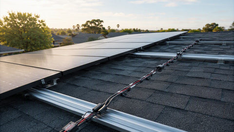
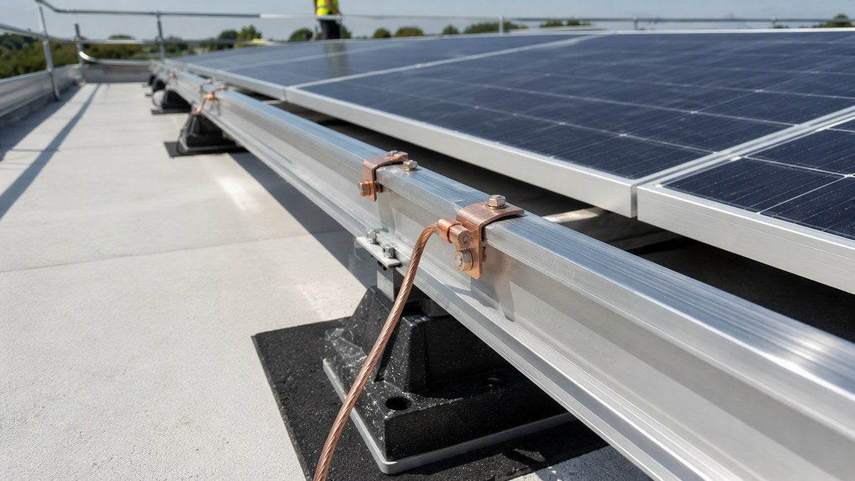
The anodized coating on aluminum module frames is an insulator — a plain bolt through the frame does nothing. Two listed approaches break through it:
| Approach | Part | Price | Notes |
|---|---|---|---|
| Integrated bonding clamp | IronRidge UFO-CL-01-B1 universal bonding clamp | $6.10 | UL 2703; clamp torque drives bonding pins through anodization — no separate lug per module |
| Bonding attachment bolt | IronRidge BHW-SQ-02-A1 bonding square bolt | $5.00 | UFO-family hardware for bonded attachment points |
| WEEB lug (module/rail) | Unirac Wiley WEEBLUG 6.7 w/ hardware | $8.66 | WEEB washer teeth pierce anodization; gas-tight bond, UL 467/2703 recognized |
| WEEB lug (K2 systems) | K2 WEEB lug 10.3 (4000622) | $5.90 | K2 rail ecosystems |
| WEEB clip | Burndy WEEB-9.5 ground clip | $2.97 | Snap-in clip bonding for compatible rails |
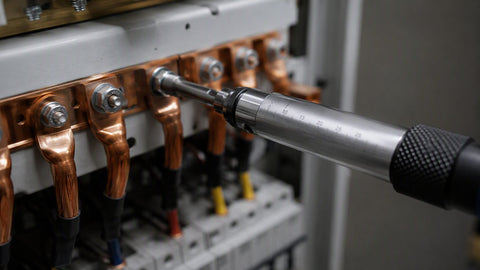
WEEB hardware earns its reputation on test data: fault currents of 1,530A for 6 seconds with post-fault resistance under 100 µΩ, and anti-rotation holding past 80 in-lb of torque. Whichever approach you pick, torque with a calibrated tool — NEC 110.3(B) and 110.14(D) make manufacturer torque values enforceable, and inspectors increasingly ask for the torque log.
BOM layer 2: rail splices, EGC termination, roof penetrations
| Function | Part | Price |
|---|---|---|
| Rail-to-rail bonding jumper | Burndy WEEB ground bonding jumper 6.7 | $12.87 |
| EGC termination lug (IronRidge) | IronRidge XR-LUG-03-A1 UFO grounding lug | $3.92 |
| Low-profile grounding lug | IronRidge GD-LUG-003 | $9.74 |
| QRail grounding lug | Quick Mount QMR-GLQ-A-50 w/ T-bolt | $8.91 |
| SnapNrack ground lug | SnapNrack 242-02101 | $4.83 |
| Flashed roof attachment (comp shingle) | QuickBOLT 17662 QB2 4IN + MicroFlash + SS-LFT | $10.85 |
Two rules inspectors enforce on this layer: rail splices must be bridged with listed bonding jumpers so continuity never depends on a bolted mechanical splice alone, and every lug must be listed for outdoor use and for bonding PV rails/modules specifically (the Burndy CL50-1TN, ILSCO GBL-4DBT and WEEB-lug families are the canonical AHJ-accepted examples). The QuickBOLT line isn't grounding hardware — it's here because commercial comp-shingle jobs live or die on flashed penetrations, and the 17662 is the mount our contractors reorder most.
EGC routing and the electrode question
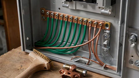
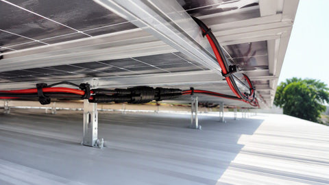
Size the EGC off Table 250.122 against the circuit's overcurrent device — for a typical 20A commercial string circuit that is #12 AWG Cu, but step up to #6 AWG wherever the conductor is exposed to physical damage. Inside the array boundary the EGC can follow its own route secured with UV-rated wire clips; the moment the homerun leaves the array, the EGC travels in the same raceway as the circuit conductors. On the electrode: a ground rod at a ground-mount array is a supplementary electrode, never a substitute — bond it to the building/service grounding electrode system so no difference of potential can exist between structures. Expect the inspector to continuity-test across splices with a micro-ohm meter and to ask for listing sheets, so keep manufacturer documentation in the permit packet.
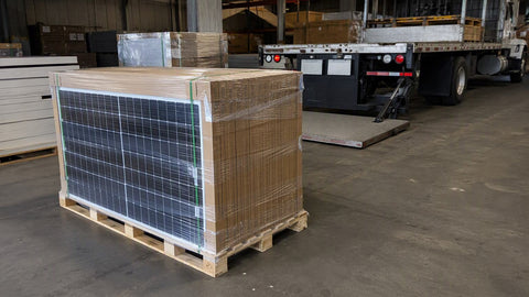
For full-system procurement — panels, 60kW-class inverters, racking and this grounding BOM quoted as one delivered package — see our commercial solar solutions page for multi-pallet and project pricing, or price the hardware directly from the IronRidge, Unirac and QuickBOLT collections.
Frequently Asked Questions
What does NEC 690.43 actually require for commercial PV?
That every exposed non-current-carrying metal part of the PV system — module frames, racking, enclosures, raceways — is connected to an equipment grounding conductor, regardless of system voltage. The clause with teeth: any device used to bond module frames or other equipment to the mounting structure must be listed, labeled and identified for that purpose — UL 2703 for module mounting/bonding hardware, UL 467 for grounding lugs. Generic hardware-store lugs and plain bolts through anodized frames do not comply, because anodization is an insulator and unlisted devices have no verified fault-current path.
What is a WEEB and why do inspectors accept it?
A WEEB (Washer, Electrical Equipment Bond — Burndy/Wiley) is a stainless washer with teeth that pierce the anodized coating on aluminum module frames and rails, embedding into bare metal to form a gas-tight, low-resistance bond without surface preparation. Inspectors accept it because it is UL 467/2703 recognized and tested for the job: fault-tested at 1,530A for 6 seconds with post-fault resistance under 100 µΩ, and anti-rotation past 80 in-lb of torque. Installed per the manufacturer's torque spec with a calibrated tool, one WEEB lug bonds a module to its rail; bonding jumpers bridge rail splices.
How do I size the equipment grounding conductor for a solar array?
Per NEC 690.45, size the EGC from Table 250.122 against the overcurrent protective device on the circuit — a 20A OCPD means #12 AWG copper, 30A means #10, 60A means #10 (Cu) per the table. If the PV circuit has no overcurrent device, assume one sized per 690.9(B) and apply Table 250.122 to that. Two adjustments: you are not required to upsize for voltage drop on an EGC, and any exposed EGC subject to physical damage must be at least #6 AWG copper per 250.120(C) — which is why many installers simply run #6 across the roof by default.
Do I need a separate ground rod for a ground-mount commercial array?
A rod at the array is permitted but optional, and it is never a substitute for bonding back to the service. NEC 690.47 lets building-mounted arrays use the building's existing grounding electrode system directly. If you drive an auxiliary electrode at a ground mount, bond it to the main grounding electrode system — an isolated rod creates a difference of potential between structures, which is precisely the hazard grounding exists to eliminate. The EGC run with the circuit conductors is the required fault-current path; electrodes handle lightning and static, not faults.
What do inspectors check on commercial solar grounding?
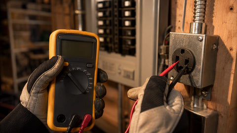
Four things, in rough order: (1) listing sheets — every bonding device documented as UL 2703/UL 467 listed for PV use, installed per instructions (NEC 110.3(B)); (2) continuity — a micro-ohm meter across rail splices and bonds, catching washers that never pierced the anodization; (3) torque logs — 110.14(D) makes manufacturer torque values enforceable, so calibrated-tool records matter; (4) EGC sizing and routing — Table 250.122 sizes, #6 minimum where exposed, EGC with circuit conductors once they leave the array. A single unbonded splice can delay Permission to Operate for weeks, which is why grounding is the leading cause of failed PV inspections.
Every Grounding Part on This Page Is In Stock
WEEB lugs, UFO bonding clamps, jumpers and lay-in lugs ship parcel same-week. Full project BOM — panels, inverter, racking, grounding — quoted as one delivered package.
Shop Grounding Hardware Contact Us for a BOM QuoteRelated Resources
- Solar grounding & bonding guide: NEC 690.43, 250 and lightning protection
- Commercial solar solutions — multi-pallet and project pricing
- IronRidge racking & grounding
- Unirac racking & WEEB hardware
- QuickBOLT mounts & flashing