Transfer Switch Wire Sizing: Ampacity Chart by Generator kW & Service Amps
Reading time: ~9 min read
📋 Key Takeaways
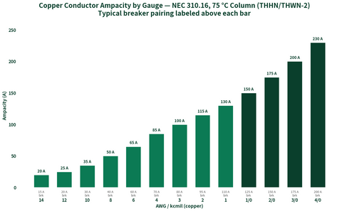
- Generator-side conductors carry a 115% multiplier. NEC 445.13 requires the conductors from the generator to the first overcurrent device to be sized at no less than 115% of the generator's nameplate current — a 22kW unit (92A at 240V) designs at 106A, which lands on 2 AWG copper at 75°C.
- Service-side conductors match the service rating. Between the meter, a service-entrance-rated ATS, and a 200A panel, you pull full-size service conductors — 3/0 Cu or 250 kcmil Al at 75°C (2/0 Cu / 4/0 Al where the NEC 310.12 dwelling 83% rule applies).
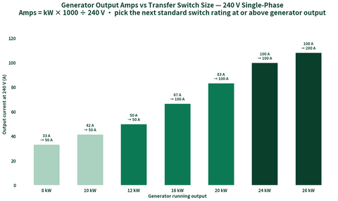
- Generator amps = kW × 1,000 ÷ 240 for single-phase standby units. Size the wire to the design amps, then round the breaker up to the next standard rating under NEC 240.4(B).
- Grounding follows the neutral, not the generator. If the ATS switches the neutral, the generator is a separately derived system under NEC 250.30 and needs its own GEC and neutral-ground bond; if it doesn't, the generator frame gets an EGC only — never bond neutral to ground twice.
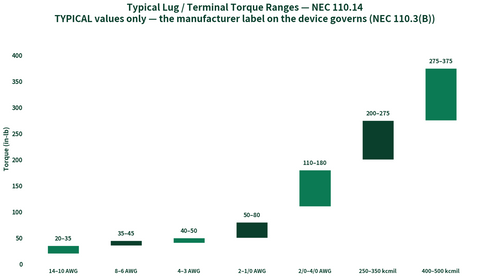
- Aluminum SER/XHHW-2 between the generator and ATS is fine on longer runs — upsize roughly two AWG steps versus copper and use listed AL9CU lugs with antioxidant and proper torque (see our lug torque chart).
The switch gets all the attention in a standby install, but the conductors between the generator, the transfer switch, and the panel are what the inspector actually measures. Undersize them and you fail on NEC 445.13 before anyone looks at the transfer equipment. Oversize them blindly and you burn money on copper you didn't need. The calculator below takes generator kW (or service amperage), conductor material, and which segment of the run you're sizing, and returns the design amps, the minimum conductor at 75°C termination ratings, the next standard breaker, and the equipment grounding conductor per NEC 250.122.
Pairing this with a standby package? Our generators collection covers air- and liquid-cooled units, and electrical supplies stocks the THHN-2/XHHW-2, SER, lugs, and conduit that complete the run. If you haven't picked the switch yet, start with our transfer switch sizing guide and come back here for the wire.
Transfer Switch Wire Size Calculator
Generator conductors size at 115% of nameplate current; service conductors at 100% of the service rating.
Ampacities from NEC 310.16 at the 75°C column (termination-limited).
Load / design current: —
Minimum conductor (75°C): —
Overcurrent device: —
Equipment grounding conductor (Cu, NEC 250.122): —
Sizing logic: generator-segment conductors per NEC 445.13 at 115% of nameplate amps, service segments at 100% of the service rating; conductors selected from NEC 310.16 (75°C); breaker rounded to the next standard size per NEC 240.6/240.4(B); EGC per NEC Table 250.122. Dwelling service conductors may use NEC 310.12 (83% rule) — shown in the note where applicable. Informational — the AHJ and the generator/ATS manufacturer instructions govern.
Generator kW to Wire Size: The Ampacity Chart
For the generator-to-ATS run at 240V single-phase, applying the NEC 445.13 115% multiplier and NEC 310.16 75°C copper ampacities:
| Generator | Nameplate amps (240V) | Design amps (×1.15) | Min. copper (75°C) | Min. aluminum (75°C) | Typical breaker |
|---|---|---|---|---|---|
| 5 kW portable | 21 A | 24 A | 10 AWG | 8 AWG | 30 A |
| 7.5 kW portable | 31 A | 36 A | 8 AWG | 6 AWG | 40 A |
| 10 kW | 42 A | 48 A | 8 AWG | 6 AWG | 50 A |
| 14 kW standby | 58 A | 67 A | 4 AWG | 3 AWG | 70 A |
| 18 kW standby | 75 A | 86 A | 3 AWG | 1 AWG | 90 A |
| 22 kW standby | 92 A | 106 A | 2 AWG | 1/0 AWG | 110 A |
| 26 kW standby | 108 A | 124 A | 1 AWG | 2/0 AWG | 125 A |
| 36 kW liquid-cooled | 150 A | 173 A | 2/0 AWG | 4/0 AWG | 175 A |
| 48 kW liquid-cooled | 200 A | 230 A | 4/0 AWG | 300 kcmil | 250 A |
| 60 kW liquid-cooled | 250 A | 288 A | 350 kcmil | 500 kcmil | 300 A |
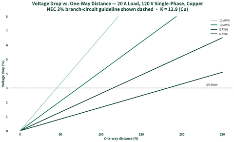
Two practical notes. First, many residential standby generators ship with a factory-installed breaker on the unit — when it does, that breaker and the manufacturer's installation manual set the floor, and NEC 110.3(B) makes those instructions enforceable. Second, long runs (75+ feet one-way) deserve a voltage-drop check: at 3% drop on 240V you only have ~7 volts to spend, and a 22kW unit on 2 AWG copper hits that wall around 110 feet. Upsize one step and move on.
Service-Side Runs: Meter to ATS to Panel
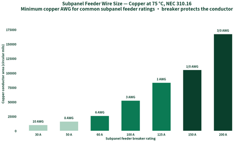
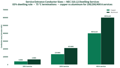
When the ATS is service-entrance rated, the segments meter → ATS and ATS → panel are service conductors, not generator conductors — no 115% multiplier, just the full service rating. The standard answers at 75°C:
| Service | Copper (310.16) | Aluminum (310.16) | Copper (310.12 dwelling) | Aluminum (310.12 dwelling) |
|---|---|---|---|---|
| 100 A | 3 AWG | 1 AWG | 4 AWG | 2 AWG |
| 150 A | 1/0 AWG | 3/0 AWG | 1 AWG | 2/0 AWG |
| 200 A | 3/0 AWG | 250 kcmil | 2/0 AWG | 4/0 AWG |
| 400 A (320 class) | 600 kcmil or parallel 3/0 | Parallel 250 kcmil | 400 kcmil | 600 kcmil |
NEC 310.12's 83% rule applies only to dwelling units where the service or feeder carries the entire dwelling load — a common case with a whole-home ATS, which is why the dwelling columns often win the job. Our service entrance cable calculator goes deeper on that table. For EGC sizing on the feeder segments, the ground wire size chart walks NEC 250.122 line by line.
Grounding and Bonding: NEC 250 Meets NEC 445
Grounding is where generator installs get red-tagged, and it hinges on one question: does the transfer switch switch the neutral?
Neutral not switched (most residential ATSs). The generator is not a separately derived system. Run an EGC with the generator conductors sized per NEC Table 250.122 from the generator breaker, bond the generator frame per the manufacturer, and leave the neutral-ground bond at the service equipment (or service-rated ATS) alone. A second bond at the generator puts neutral current on the grounding path — an instant defect.
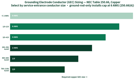
Neutral switched (3-pole ATS, separately derived system). NEC 250.30 now applies: the generator needs its own neutral-ground bonding jumper, a grounding electrode conductor per NEC 250.66 to a suitable electrode, and the EGC still accompanies the conductors per 250.122. NEC 445.11 and the generator listing dictate where that bond happens — follow the transfer switch schematic exactly, because the neutral must be bonded in exactly one place at a time as the switch transfers.
Ground rods at the generator do not substitute for the EGC. A rod bonds to earth for lightning and surges; the EGC is the fault-return path that actually trips the breaker. Both, in the right places, per 250.4(A).
Frequently Asked Questions
What size wire do I need for a 22kW generator to the transfer switch?
2 AWG copper or 1/0 AWG aluminum at 75°C termination ratings, protected at 110A. A 22kW unit produces 92A at 240V; NEC 445.13 requires conductors rated at 115% of nameplate (106A), and 2 AWG copper carries 115A per NEC 310.16. Check the unit's installation manual first — if the factory breaker differs, the manufacturer's instructions govern under NEC 110.3(B).
Does the NEC really require 115% ampacity on generator conductors?
Yes — NEC 445.13 requires the ampacity of conductors from the generator terminals to the first distribution device containing overcurrent protection to be at least 115% of the generator's nameplate current rating, unless the generator design prevents sustained overload. In practice, applying 115% everywhere is the safe default and what most inspectors expect to see.
Do I need a ground rod at the generator?
Only when the transfer switch switches the neutral, making the generator a separately derived system under NEC 250.30 — then a grounding electrode connection per 250.66 is required. With a non-switched neutral, the EGC run with the conductors handles fault current and a rod adds nothing to fault clearing. Bonding neutral to ground at both the generator and the service is a code violation either way unless the switch design requires it.
What size ground wire runs with the generator conductors?
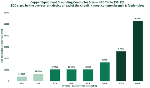
The equipment grounding conductor sizes off the overcurrent device per NEC Table 250.122 — for example, a 110A breaker on a 22kW generator run takes 6 AWG copper, a 70A breaker on a 14kW takes 8 AWG, and a 50A breaker on a 10kW takes 10 AWG. Where conductors are upsized for voltage drop, NEC 250.122(B) requires the EGC to be upsized proportionally.
Can I use aluminum wire between the generator and the ATS?
Yes — XHHW-2 or SER aluminum is common on longer generator runs and costs roughly half of copper at these sizes. Expect to upsize about two AWG steps (a 22kW run goes from 2 AWG Cu to 1/0 Al), use lugs listed AL9CU or AL-rated for the conductor, apply oxide inhibitor, and torque to the equipment marking per NEC 110.14. Verify the ATS and generator lugs accept aluminum before ordering.
Wiring a Standby Package?
PES Supply stocks THHN-2, XHHW-2, SER, service-rated ATSs, and listed lugs from 169 authorized brands. Send the generator spec and one-line — we'll quote the complete wire-and-switch package at contractor pricing.
Shop Generators Contact Us for Bulk PricingRelated Resources
- Transfer switch sizing guide: amps, circuits, and ATS vs manual
- Ground wire size chart: NEC 250.122 EGC sizing
- Service entrance cable size calculator: 100A–400A
- Standby and portable generators
- Wire, conduit, lugs, and transfer equipment