Updated September 2026 — refreshed against the live PES catalog; product pricing verified 2026-09-26.
Every August we get the same wave of phone calls: a storm knocked out power for nine hours, the freezer is a loss, and the homeowner just bought a 7,500-watt portable generator at the big-box store with a plan to "backfeed through the dryer outlet." Stop right there. Backfeeding kills linemen, voids your insurance, and violates NEC 702 five ways before breakfast. The legal, safe bridge between your generator and your house is a transfer switch — and choosing between manual and automatic is a decision you'll live with for twenty years. This guide walks through both types, the NEC and UL standards that govern them, real sizing math, and the installed costs we actually charge in 2026.
What a Transfer Switch Actually Does (and Why the Code Demands One)
A transfer switch is a double-throw switch: your house loads connect to either the utility or the generator, never both at once. That mechanical or electrical interlock is the entire point — it makes it physically impossible for your generator to push 240 volts back up the utility line and into a repair crew's worksite. NEC 702.5 requires a means of transfer for any optional standby system, and 702.6(B) specifically bans interconnection methods that can backfeed. A $15 dryer cord and good intentions are not a transfer means. Every AHJ inspector in America will red-tag that, and every insurance adjuster after a fire will find it.
Beyond the legal floor, the switch also manages load. A standby generator can't carry everything in a modern all-electric home, so transfer equipment decides which circuits get generator power and which stay dark. That load management is where the real design work happens — and where most DIY installs go sideways.
Manual Transfer Switches (MTS): Simple, Cheap, Reliable
A manual transfer switch is a row of toggles — typically 6 to 10 circuits on a residential unit — wired between your main panel and a generator inlet box on the outside wall. When the power fails, you wheel out the generator, plug the cord into the inlet, start it up, walk to the switch, and flip each circuit from LINE to GEN. Total restoration time: five to ten minutes if you're home and the generator starts on the first pull.
The appeal is honesty. There's almost nothing to fail: no control board, no battery charger, no exercise clock. We've serviced MTS panels installed in the mid-1990s that still transfer cleanly. The drawbacks are equally plain. You must be home. You must be willing to go outside in the ice storm. And you're limited to the circuits on the switch — usually 30 or 50 amps worth, which means a portable generator in the 5,000–9,500 watt class feeding essentials: fridge, furnace blower, a few lights, the well pump if you're lucky, and the internet so the kids don't revolt.
Reliance and Generac both make solid 10-circuit MTS panels; pair them with a proper power inlet box (NEMA L14-30 for 30A, CS6375 for 50A) and you have a code-compliant whole-essentials setup for well under $1,500 installed. Browse our transfer switch inventory for current models and amperages.
Interlock Kits: The Budget Middle Path
For main panels, a listed interlock kit (Siemens, Square D, Eaton, and GE all have OEM kits for many panel lines) physically prevents the main breaker and a backfeed generator breaker from being on simultaneously. It's legal where the AHJ accepts it — most do, provided the kit is listed for that specific panel per NEC 110.3(B) — and it lets you feed any circuit in the panel rather than a fixed set of six. Cost: $50–150 for the kit plus a 30–50A two-pole breaker and an inlet. The catch is discipline. Nothing stops you from running the AC compressor on a 7 kW generator and stalling it flat except your own judgment. With an interlock, load management is a human being with a list taped to the panel door. Write that list. We've pulled more than one stalled generator out of a garage where someone forgot the water heater was on.
Automatic Transfer Switches (ATS): The Standby Generator's Brain
An automatic transfer switch monitors utility power constantly. When voltage drops out — typically for 3–10 seconds, to ride through momentary flickers — the ATS signals the standby generator to start, waits for it to stabilize at rated voltage and frequency, then transfers the load. When the utility returns and stays stable for a cool-down window, it transfers back and shuts the generator down. Nobody touches anything. That's the whole value proposition: the power fails at 2 a.m. while you're in Denver for a conference, and your house in the ice storm keeps its heat, its sump pump, and its refrigerator without you.
UL 1008 Standard for Transfer Switch Equipment
Residential ATS units come in two flavors. Service-entrance rated (200A typical) sit between the meter and your main panel — the whole house is on generator, with load-shedding modules dropping the AC compressor or water heater if the generator approaches its limit. Load-side ATS feed only a subpanel of critical circuits. Service-entrance is cleaner for whole-home standby units in the 14–26 kW class; the NEC 230.82 and 702 rules around service equipment make the install straightforward when the ATS carries the service disconnect label. All of this equipment must be listed to UL 1008, the transfer switch standard — a $400 no-name box off an auction site without the UL 1008 mark is not a transfer switch, it's a liability with lugs.
Open Transition vs. Closed Transition
Open Transition (Break-Before-Make)
Closed Transition (Make-Before-Break)
Every residential ATS you'll buy is open transition — break-before-make. There's a deliberate 100–300 millisecond dead spot while the switch moves from utility to generator. Lights blink, computers on UPS don't notice, clocks reset. Closed transition (make-before-break) briefly parallels the generator with the utility for a seamless transfer, and it requires utility approval, sync-check relays, and costs that start where residential budgets end. Unless you're powering a home dialysis machine or a server closet that can't blink, open transition is the right answer. Don't let a salesman upsell you into closed transition for a house.
Sizing the Switch: Amps, Volts, and the Numbers That Matter
Service Entrance Rating
The transfer switch amperage must match what passes through it. For a service-entrance ATS on a 200A service, that's a 200A switch, full stop — NEC 702.5 and the UL 1008 listing require it to carry the full service load even though the generator will never supply that much. For an MTS or load-side ATS, size to the generator's output breaker: a 30A inlet and 30A switch for a 7.5 kW portable, 50A for a 12 kW. Voltage is simple — 120/240V single phase for everything residential — but check the short-circuit rating. Service equipment sees the full fault current of the utility transformer; a 22 kAIC rating is the residential norm, and your AHJ will ask.
| Generator class | Max continuous output @240V | Transfer equipment match | Typical coverage | Installed cost range 2026 |
|---|---|---|---|---|
| 5.0–7.5 kW portable | 21–31A | 30A MTS or 30A interlock + inlet | 6–10 essential circuits | $900–1,500 |
| 9.5–12 kW portable | 40–50A | 50A MTS (CS6375 inlet) | Essentials + well pump or one mini-split | $1,200–1,900 |
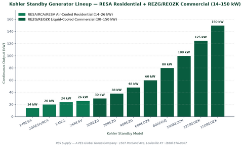
| 14–18 kW standby | 58–75A | 100A load-side ATS or 200A SE ATS with shedding | Most of the house, managed AC | $5,500–8,000 (incl. generator) |
| 20–22 kW standby | 83–92A | 200A service-entrance ATS | Whole home incl. 4-ton AC with soft start | $8,500–11,500 (incl. generator) |
| 24–26 kW standby | 100–108A | 200A SE ATS | Whole home, minimal management | $10,500–14,000 (incl. generator) |
For the feeders between generator, ATS, and panel, run the numbers through our NEC wire sizing and ampacity guide and cross-check with the wire ampacity chart. A 100A standby feed wants 2 AWG copper minimum (3 AWG only under specific conditions), and the run from a 22 kW unit's 100A breaker to a service-entrance ATS is not the place to discover voltage drop at 60 feet.
NEC 702: The Rules Your Inspector Will Actually Check
Article 702 covers optional standby systems, and the sections inspectors cite most are these: 702.5, transfer equipment required; 702.6, prohibition of interconnection that can backfeed; 702.7(B), the requirement for a permanent sign at the service equipment indicating the type and location of the standby source; and 702.12, which sets rules when a portable or vehicle-mounted generator is the source. Separately, NEC 445.18 requires a generator disconnecting means, and 250.35 governs grounding — whether the generator is a separately derived system determines if you switch the neutral (3-pole transfer) or not (2-pole). Get this wrong and you'll have two grounding points fighting each other, nuisance GFCI trips, and an inspector writing corrections. Most residential standby generators bond neutral-to-frame and are configured non-separately-derived with a 2-pole ATS; verify your specific model's manual before rough-in, because switching a bonded neutral through a 2-pole switch is a genuine code violation that also creates shock hazards.
NEC 702 Requirements for Optional Standby Systems
| NEC section | Requirement | Field note |
|---|---|---|
| 702.5 | Transfer equipment on all optional standby systems | The reason backfeed cords are illegal |
| 702.6(B) | No interconnection capable of inadvertent interconnection | Interlocks must be listed for the panel |
| 702.7(B) | Permanent signage at service equipment | $8 engraved tag; inspectors check it |
| 702.12 | Rules for portable generator connection | Inlet box must be listed and rated |
| 250.35 | Grounding of separately derived systems | Determines 2-pole vs 3-pole transfer |
| 445.18 | Generator disconnecting means | Usually the unit's main breaker |
| 700/701/702 distinction | Only 700/701 are "required" systems | Residential standby is optional = 702 rules |
Installation: What the Job Actually Looks Like
A service-entrance ATS install is a half-day for two electricians with a utility disconnect appointment: pull the meter (utility does it), land the service conductors on the ATS, feed the main panel from the ATS load lugs, run the generator feeders, and commission the control wiring. Load-side ATS and MTS jobs skip the utility visit. The part homeowners underestimate is the gas or propane plumbing — a 22 kW standby unit drinks 3.6 gallons of propane an hour at full load, and undersized gas piping is the single most common defect we find in standby installs done by HVAC-only crews. One-inch minimum for most 14–22 kW runs over 20 feet, and have the plumber verify delivered pressure under load, not static.
Portable generator hookup, step by step
- Wheel the generator outside, 15+ feet from windows and doors. Carbon monoxide is the leading killer in every storm aftermath report; never in the garage, never under the deck.
- Connect the cord from the generator's 240V outlet to the inlet box before starting anything.
- Start the generator and let it stabilize two minutes with no load.
- Flip transfer circuits one at a time from LINE to GEN, biggest motor first (well pump, furnace), watching the generator recover between flips.
- Stay under the budget: total running watts below 80% of generator rating. Electric water heaters and central AC are almost always off the list on portable units.
- Reverse the sequence when utility returns, generator breaker off before unplugging, and run the generator dry of fuel monthly if it sits.
Cost Reality Check, 2026
| Path | Equipment | Labor + permits | Total typical | Restoration time |
|---|---|---|---|---|
| Interlock + inlet (portable gen) | $150–350 | $350–600 | $500–950 | 5–10 min, manual |
| 10-circuit MTS + inlet | $400–650 | $500–850 | $900–1,500 | 5–10 min, manual |
| Load-side ATS + 14 kW standby | $4,200–5,400 | $1,800–2,800 | $6,000–8,200 | ~30 sec, automatic |
| Service-entrance ATS + 22 kW standby | $6,800–8,600 | $2,200–3,400 | $9,000–12,000 | ~30 sec, automatic |
| SE ATS + 26 kW standby, long gas run | $8,200–10,000 | $3,000–4,500 | $11,200–14,500 | ~30 sec, automatic |
Cost Comparison: MTS vs ATS
Generator selection drives half this budget; our whole-home generator sizing guide and the breakdowns of 26 kW units and 22 kW units cover the machine side, and this sizing walkthrough matches kW to your actual load list. For the generators themselves, see our 10–14 kW standby and 10–15 kW collections. And if your backup strategy leans toward batteries instead of combustion, the PWRcell cost guide and backup runtime calculator frame the honest comparison.
Maintenance: The Part Everyone Skips
A standby generator that doesn't exercise is a $9,000 lawn ornament with stale fuel. Weekly self-test (the ATS schedules it — 12 minutes, no load transfer) keeps the engine alive; annually, oil and filter, spark plugs every two to three years, battery every three to four, and a full-load test once a year where you actually transfer the house for 30 minutes. For MTS and interlocks, the maintenance is a flashlight and ten minutes: operate each toggle once a year, check the inlet box for corrosion and insect nests, and verify the generator actually starts. The time to discover a dead starter battery is a calm Saturday, not the night the ice storm takes the grid down.
Load Management Math: What a Generator Can Really Carry
The most abused number in the generator world is the nameplate wattage. A "9,500-watt" portable delivers 9,500 starting watts and 7,500 running watts; plan your life around the running number and keep 20% in reserve, so the honest budget is 6,000 watts. Here's the load table we tape inside every MTS panel we install — measured values from field clamp meters, not nameplate optimism:
| Circuit / appliance | Running watts (typical) | Starting surge | Portable-gen verdict |
|---|---|---|---|
| Refrigerator (modern, 21 cu ft) | 150–250W | 600–1,200W | Always on the list |
| Gas furnace blower (1/2 HP) | 600–800W | 1,800–2,400W | Yes — heat is the priority |
| Well pump (1/2 HP, 240V) | 900–1,100W | 2,500–3,200W | 50A setups only; watch the surge |
| Sump pump (1/3 HP) | 800W | 1,300–2,000W | Yes in flood season |
| 10 LED light circuits | 150–300W total | None | Trivial; leave them on |
| Internet + laptops + TV | 200–400W | None (switch-mode PSUs) | Yes; morale is a load too |
| Microwave | 1,000–1,500W | ~2× running (none on inverter models) | Yes, alone; don't stack with pump starts |
| Electric water heater | 4,500W | None (resistive) | No on portable; managed on standby |
| Central AC (3.5 ton) | 3,500–4,200W | 9,000–14,000W | No on portable; soft start + 18 kW minimum |
| Level 2 EV charger (40A) | 9,600W | None (EVSE ramps load) | No; charge from utility only |
Add your picks, keep running total under 80% of generator rating, and respect starting surges one motor at a time. This is why we like the 50A MTS on a 10–12 kW portable for rural homes with wells — the extra amperage headroom is what absorbs that 3,000-watt pump surge without browning out the furnace board and throwing an ignition fault at midnight.
Decision Matrix: Interlock vs. MTS vs. ATS
After a few hundred of these conversations, the decision collapses to four questions. Are you ever away from home for more than a day in storm season? If yes, manual options are out — pipes freeze on their own schedule. Is your must-run load list under 6,000 watts and generator-portable? Then a $1,200 MTS job beats a $9,000 standby system by enough money to matter. Do you have natural gas or a big propane tank already? That tilts hard toward standby. And what's the outage profile — two-hour blips or multi-day ice events? Blips favor batteries or tolerance; ice storms favor combustion. The homes where we install ATS units without hesitation: medical equipment in the house, sump pumps with finished basements, home businesses with servers, and anyone who simply refuses to do outage chores at 3 a.m. Ever again.
Fuel and Runtime: Planning the Long Outage
A 20–22 kW air-cooled standby unit burns roughly 2.1 gallons of propane per hour at half load — call it 50 gallons a day running moderately. A 500-gallon propane tank (400 usable) buys you about eight days of part-time running, which covers virtually every residential outage in North American history. Natural gas removes the tank math entirely; your constraint becomes the utility's gas pressure during regional events, which historically holds better than the electric grid in the same storm. Portables are the weak link: 5 gallons of gasoline is 8–10 hours at half load, and after day two you're in the gas-station line with everyone else. Stabilize stored fuel, rotate it every six months, and keep 20 gallons minimum if a portable is your plan. The people who weather ice storms comfortably are the ones who treated fuel like inventory, not an errand.
Frequently Asked Questions
Is an interlock kit as safe as a transfer switch?
When the kit is listed for your specific panel model and installed per its instructions, yes — the mechanical interlock makes simultaneous utility and generator connection physically impossible, same as a switch. The difference is circuit control: an interlock leaves load management to you, with no fixed limits.
Can I install a manual transfer switch myself?
It's a panel-adjacent wiring job that most jurisdictions require to be permitted and inspected, and many require a licensed electrician. Handy homeowners do pass inspection on MTS installs, but the permit and inspection are not optional. Budget the inspection fee either way.
How long does an ATS take to restore power?
Typically 20–40 seconds: a few seconds of outage confirmation, 10–15 seconds of generator crank and stabilization, then transfer. Sensitive electronics should be on small UPS units to ride through the gap.
Do I need a 3-pole transfer switch?
Only if your generator is configured as a separately derived system (neutral switched). Most residential standby units ship bonded-neutral and use a standard 2-pole ATS. Check the generator manual's wiring diagram — getting this wrong creates parallel neutral paths and code violations.
Will a 22 kW generator run my whole house?
For most homes up to about 3,000 sq ft with gas heat and water heating, yes, including a 4-ton AC with a soft starter. All-electric homes with multiple compressors, electric ranges, and EV charging need load management or a larger unit. Run your actual load list before sizing.
Can a transfer switch work with a solar battery system instead of a generator?
Transfer Switch Sizing
Yes — hybrid inverters have an internal automatic transfer function that switches to battery in milliseconds, faster than any ATS. The ATS remains the right tool when the backup source is a combustion generator or when you need a generator to supplement a battery inverter during long outages.
Sources and Standards
NEC 2023 Articles 230.82, 250.35, 445.18, and 702; UL 1008 (Transfer Switch Equipment); NFPA 110 for context on standby system classes. Equipment in this guide is drawn from our transfer switch shelves and standby generator lines — standby home generators and whole-house generator options — installed across the Pacific Northwest storm belt since 2019.