Updated September 2026 — content reviewed and refreshed by the PES team. For current pricing and availability, see the linked product pages or request a quote.
Solar Permitting Guide: NEC Requirements, AHJ Approval Process, and Inspection Checklist
Reading time: ~18 min · Updated for NEC 2023/2026 adoption cycles
Permitting is where good solar jobs go to die. Not on the roof, not in the design software — in the plan-review queue of an Authority Having Jurisdiction (AHJ) that bounced your package because the one-line diagram was missing a temperature-corrected voltage calc. I've watched a 9 kW residential job sit for five weeks over a missing UL 3741 listing note. Five weeks. The fix took eleven minutes.
This guide is the framework we use to get permit packages through plan review on the first submission: what NEC Articles 690 and 705 actually require, which documents every AHJ wants, why applications get rejected, and the inspection checklist we run before the inspector ever pulls into the driveway. It is written for electricians, solar installers, and EPC contractors — not homeowners.
PES Supply stocks the balance-of-system gear these inspections hinge on — breakers and electrical supplies, charge controllers, listed inverters, and transfer equipment — 50,000+ SKUs from 169 authorized brands with 7–10 business day delivery.
Solar permitting sits on three layers of authority, and confusing them is the first way packages die:
- NEC (NFPA 70): Article 690 covers PV systems under 5,000 kW; Article 691 covers large-scale supply stations; Article 705 governs interconnection with the utility; Article 706 covers energy storage. The NEC is a model code — it has no force until a state or municipality adopts it.
- Building and fire codes: The IRC (R324) and IFC (1205) control roof access pathways, ridge setbacks, and structural attachment. Structural review runs under ASCE 7 wind and snow load provisions.
- The utility: Interconnection approval is a separate track from the building permit. NERC and IEEE 1547 sit underneath the utility's own tariff and interconnection agreement.
The AHJ enforces whichever NEC edition it has adopted — not the newest one. As of mid-2026 the country is split: a large share of jurisdictions still enforce NEC 2020, most of the rest are on NEC 2023, and early adopters (Colorado effective August 1, 2026; Massachusetts with state amendments) have moved to NEC 2026. Designing a 2026-edition plan set for a 2020-edition AHJ is a guaranteed correction notice.
| NEC Edition | Adoption Status (mid-2026) | What Changes for PV Plan Sets |
|---|---|---|
| NEC 2017 | Shrinking minority of AHJs | Older rapid-shutdown language (module-level vs. array boundary 2017 rules); different 705.12 structure |
| NEC 2020 | Still common | 80V/30-second inside-boundary rule; 1,000V dwelling limit; PV SPD not yet mandated |
| NEC 2023 | Most common current edition | PV hazard control systems per UL 3741; bifacial Isc basis; "PV SPD" required at combiners/disconnects; PV wire per UL 4703 |
| NEC 2026 | Early adopters (CO, MA) | Fractions-of-ampere rule 690.4(G); 100 kW engineering threshold removed; E-stop RSD initiation allowed; labeling consolidated at 690.7(D)/690.12(D) |
Field note
First thing I do on any job in a new jurisdiction: call the plans examiner and ask two questions — which NEC edition is adopted, and do they have a written solar checklist. Ten minutes on the phone has saved me more resubmittals than any software ever has.
Article 690 is 40+ pages of code. Plan reviewers concentrate on five areas. Get these right and the rest of the package rarely gets touched.
2.1 Maximum Voltage — 690.7
Maximum system voltage is the sum of series module Voc, corrected for the coldest expected ambient temperature. On one- and two-family dwellings, DC circuits cannot exceed 1,000 volts; most string designs target 600V conductors anyway. The correction uses the module's Voc temperature coefficient against the ASHRAE extreme minimum for your site — or NEC Table 690.7(A) correction factors if your AHJ allows the table method.
| Design Step (10 × 450W string, Voc 49.6V, β Voc −0.27%/°C) | Math | Result |
|---|---|---|
| Base string Voc at STC (25°C) | 10 × 49.6V | 496V |
| Site extreme min temp (ASHRAE, e.g. Louisville KY) | −15°C → ΔT = 40°C | 40°C below STC |
| Voltage rise | 496V × (0.0027 × 40) | +53.6V |
| Cold-corrected max voltage | 496 + 53.6 | 549.6V |
| Check vs. limits | < 600V conductor rating, < 1,000V dwelling cap, < inverter max input | Pass |
Miss this correction and a plan reviewer in a cold climate will bounce the package every time. It's the single most common math error we see on residential one-lines.
2.2 Circuit Sizing — 690.8
Maximum PV source-circuit current is Isc × 125%. Conductors then carry a second 125% factor (156% of Isc total) after temperature and conduit-fill adjustment. Inverter output circuit conductors size at 125% of continuous inverter output current. Under NEC 2026 the new 690.4(G) fractions-of-ampere rule means you carry decimals through the calc instead of rounding down — designs sitting at the edge of a conductor size can get pushed to the next size up.
| Sizing Step (2 parallel strings, Isc 11.4A each) | Math | Result |
|---|---|---|
| Maximum source-circuit current | (11.4A + 11.4A) × 1.25 | 28.5A |
| Conductor ampacity required (before adjustments) | 28.5A × 1.25 | 35.6A |
| Candidate conductor | 10 AWG PV Wire, 90°C, Table 310.16 | 40A base ampacity |
| Adjustment: 45°C rooftop ambient (310.15(B)) | 40A × 0.87 | 34.8A |
| Adjustment: 4 current-carrying conductors in conduit (×0.8) | 34.8A × 0.80 | 27.8A |
| Verdict | 27.8A < 35.6A required | Fail — bump to 8 AWG or split conduit runs |
That last row is why reviewers want to see the full adjustment chain on the one-line. A 10 AWG run that looks fine at STC fails after rooftop temperature and conduit fill. Show the factors, not just the final size.
2.3 Rapid Shutdown — 690.12
Still the most-scrutinized section in residential review. The performance targets: conductors more than 1 foot outside the array boundary drop to 30V or less within 30 seconds of initiation; inside the boundary, 80V within 30 seconds (or a listed PV hazard control system per UL 3741). Initiation devices must be readily accessible — for one- and two-family dwellings, at an outdoor location. NEC 2026 reorganizes this under 690.12(C) and explicitly permits listed E-stop style switches as initiation devices.
2.4 Arc-Fault Protection — 690.11
PV systems with DC circuits at 80V or more on or penetrating a building need listed PV arc-fault protection. Nearly every modern string inverter has this built in; if yours doesn't, the plan reviewer will ask where it is.
2.5 Surge Protection — 690.35 (2023+)
Under NEC 2023, PV DC circuits require a listed "PV SPD" at the combiner, power converter, or DC disconnect. This catches installers running 2020-era templates — the SPD line item is now a plan-check item, not an option. We stock surge and BOS components in the electrical supplies catalog.
705.12(B) load-side connections live and die on busbar math. The rule most reviewers quote: the sum of the main breaker plus the PV backfeed breaker cannot exceed 120% of the busbar rating (with the PV breaker at the opposite end of the bus from the main).
| Scenario | Math | Max PV Breaker | Verdict |
|---|---|---|---|
| 200A panel, 200A bus, 200A main | (200 × 1.2) − 200 | 40A | Standard 7.6–9.6 kW system fits |
| 200A panel, 225A bus, 200A main | (225 × 1.2) − 200 | 70A | Room for larger systems |
| 100A panel, 100A bus, 100A main | (100 × 1.2) − 100 | 20A | ~3.8 kW max — usually forces a derate or panel upgrade |
| Main derated: 200A bus, 175A main | (200 × 1.2) − 175 | 65A | Derating the main buys backfeed capacity |
| Supply-side tap (705.12(A)) | PV OCPD sized to conductors, not busbar | System-dependent | Bypasses 120% rule entirely; needs tap-compliant equipment |
Disconnecting means under 705.20 must be manually operable, lockable open per 110.25, and installed per 230.70-series service rules. Labeling at the service equipment — "SOLAR ELECTRIC SYSTEM CONNECTED" plus disconnect location — falls under 705.10 and is one of the cheapest inspection failures to avoid. When the 120% math doesn't work, we usually move to a supply-side connection or a line-side tap ahead of the main; the gear for that lives in our transfer switches and interconnection hardware category.
One more interconnection detail that catches crews: NEC 2026 reinstates a conductor-length limit under 705.11(C)(1) between the interconnection point and the overcurrent protection device. On systems where the inverter sits a long feeder away from the service — detached garages, barns, ground-mounts trenched to the house — measure that run during design, not during rough-in. We've seen a 90-foot tap conductor force a redesign that a tape measure at the site survey would have prevented. Keep the interconnection conductor short, protected, and documented on the one-line with its actual length.
Requirements vary, but this is the package that survives plan review in the overwhelming majority of AHJs:
| Document | Description | Typically Required |
|---|---|---|
| Site plan | Property lines, building footprint, array location, equipment placement, setbacks, disconnect locations | Yes |
| Roof plan | Array layout, module spacing, fire access pathways, ridge setbacks, penetrations | Yes (roof-mount) |
| One-line electrical diagram | Every component, conductor size, OCPD, disconnect, grounding, and label callout | Yes |
| Module datasheet | Voc, Isc, Vmp, Imp, temperature coefficients, UL 61730 listing | Yes |
| Inverter datasheet | Input/output ratings, UL 1741 (SB where mandated) certification | Yes |
| Racking engineering letter | PE-stamped structural certification for roof load, wind uplift, attachment spacing | Yes (most AHJs) |
| Battery documentation | UL 9540 listing, installation manual, ventilation and clearance requirements | Yes (with storage) |
| Load calculation / busbar worksheet | 705.12 math showing busbar rating, main, and backfeed breaker | Yes |
| Contractor license | Electrical and/or solar license per state law | Yes |
The one-line diagram carries the package. It must show string configuration, module ratings, cold-corrected maximum voltage, Isc × 125% current calcs, conductor types and sizes (e.g. 10 AWG PV Wire, 90°C), conduit and fill where applicable, every OCPD, both disconnects, inverter model and AC output, EGC sizing per 250.122, the interconnection point with busbar math, rapid shutdown equipment and boundaries, and every required label. Our Listed inverters come with the datasheets reviewers ask for.
Run the building permit and the utility interconnection in parallel. The utility clock is often the longer one, and PTO can't happen until both tracks finish.
| Phase | Typical Duration | What Happens | Failure Mode to Avoid |
|---|---|---|---|
| Pre-application | 1–3 days | Pull AHJ checklist, confirm NEC edition, check zoning/HOA, start utility interconnection app | Designing to the wrong code edition |
| Submission | 1 day | Complete package + fees (per-kW, valuation-based, or flat) | Missing PE letter or datasheets |
| Plan review | 2–4 weeks (same-day with SolarAPP+) | Reviewer checks one-line, structural, fire access | Incomplete voltage/ampacity math |
| Correction cycle (if needed) | +1–2 weeks each | Address comments, resubmit | Partial responses that re-trigger review |
| Rough-in inspection | Scheduled within days | Conduit, wiring, boxes before close-up | Unsupported PV wire, wrong raceway indoors |
| Final inspection | 1 visit | Labels, disconnects, RSD function, grounding | Missing labels; RSD not demonstrated |
| Utility PTO | 1–4 weeks after final | Meter swap/witness test, permission to operate | Energizing before PTO — don't |
Many AHJs have adopted SolarAPP+ or the Solar ABCs expedited process for residential systems under ~10 kW: standardized forms, pre-approved mounting details, same-day or next-day approval. Ask before you submit the long way.
| Rejection Reason | Code Reference | How to Avoid |
|---|---|---|
| Incomplete one-line diagram | 690.1, 690.8 | Every rating, conductor, OCPD, and disconnect on the sheet |
| Voltage not temperature-corrected | 690.7 | ASHRAE extreme-min correction shown in the calc block |
| 120% rule violation | 705.12(B) | Show busbar math; derate main or go supply-side |
| Rapid shutdown listing missing | 690.12 | Call out UL 3741 PVHCS or listed MLPE explicitly |
| Ampacity not derated | 690.8(B), 310.15 | Show ambient-temp and conduit-fill adjustment factors |
| No structural letter | Building code / ASCE 7 | PE stamp for wind, snow, attachment |
| Inverter not listed | 690.4, UL 1741 | Include certification page, UL 1741 SB where required |
| Label schedule missing | 690.13(C), 705.10 | Label table on the plan set, not just the hardware |
| Working clearances not shown | 110.26 | 3-ft clearance drawn in front of all equipment |
| Fire pathways absent | IRC R324 / IFC 1205 | 36-in pathways and 18-in ridge setback on roof plan |
A complete package doesn't just pass faster — it builds a reputation with the plans examiner. Reviewers remember contractors whose submittals never bounce, and the tone of the whole relationship changes.
We've pulled permits across enough jurisdictions to know that first-pass inspection success is a checklist problem, not a luck problem. Run this the day before the inspector arrives:
General
- Permit card and approved (stamped) plan set physically on site
- 3-ft working clearance in front of every piece of energized equipment (110.26)
- All equipment installed per manufacturer instructions — the inspector has them
Array and DC wiring
- Modules match approved plans exactly — make, model, count
- PV Wire or USE-2 for exposed runs (690.31(C)); supported within 24 inches; no contact with roof surface
- DC inside the building in metal raceway or MC (690.31(E))
- Connectors fully mated, same-brand pairs, torque per manufacturer
Disconnects, OCPD, grounding
- DC disconnect rated for system DC voltage, marked "PV SYSTEM DISCONNECT" (690.13(C)), lockable open
- OCPDs marked "PV" (690.9(D)); combiner fuses sized per plan
- EGC per Table 250.122; GEC landed per 690.47; module-to-rail bonding via listed UL 2703 devices
Inverter, RSD, labels
- Inverter UL 1741 (SB where adopted); AC conductors at 125% of output current
- RSD initiation device at a readily accessible outdoor location (dwellings); demonstrate the shutdown if asked
- Every label installed: DC disconnect ratings, AC interconnection label, service-equipment "SOLAR ELECTRIC SYSTEM CONNECTED," rapid shutdown plaque
| Location | Required Label | NEC Reference |
|---|---|---|
| DC disconnect | "PV SYSTEM DISCONNECT" plus rated max voltage, current, Isc | 690.13(C) |
| AC interconnection breaker | "SOLAR ELECTRIC SYSTEM CONNECTED" | 705.10 |
| Service equipment | Interconnected power source warning + disconnect location | 705.10 |
| RSD initiation device | Rapid shutdown identification plaque | 690.12 / 690.56(C) |
| DC OCPD | Devices marked "PV" or "Photovoltaic" | 690.9(D) |
| Battery system | ESS disconnect ID, voltage, available fault current | 706.10 / 480 |
Labels must be permanent and weather-resistant outdoors. Engraved or UV-stable printed labels survive; a label-maker tape strip in the Kentucky sun does not. Inspectors check, and they should.
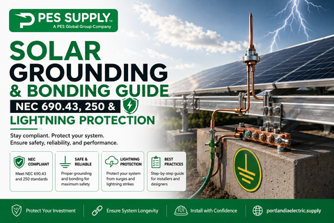
Grounding failures are quiet failures — the system works fine until a fault, a lightning strike, or an insurance claim. The plan set and the install need to agree on four things. First, module-to-rail bonding: listed UL 2703 bonding devices, one per module-to-rail interface unless the racking system is listed as an integrated bonding system. Second, rail-to-rail bonding across splices — a mechanical splice is not automatically an electrical bond unless the manufacturer lists it as one. Third, the equipment grounding conductor sized from Table 250.122 off the rating of the overcurrent device protecting the circuit, landed at the inverter and carried to the array. Fourth, the grounding electrode connection per 690.47 — on interactive systems this usually means bonding into the existing building grounding electrode system, not driving a new isolated rod and calling it done.
Two mistakes show up in the field constantly: a second ground rod installed but never bonded to the service GES (creating a difference-of-potential hazard), and copper EGC run in contact with aluminum rail without a listed transition fitting. Both are inspection failures; both are corrosion or shock hazards five winters later. Torque the lugs to the value printed on the device — "hand tight plus a quarter turn" is not a torque spec, and infrared scans on commissioning day will find the loose ones.
Add a battery and the permit package grows a second spine. Article 706 (and Article 480 for legacy chemistries) layers on top of 690, and the AHJ's fire marshal usually joins the review. The documents that matter: the UL 9540 listing for the complete ESS (not just the cells — the system), the manufacturer's installation manual with clearances and ventilation requirements, and the disconnecting-means plan. Many AHJs now ask for the UL 9540A thermal-runaway test report on larger residential and all commercial storage jobs.
Practical placement rules reviewers enforce: minimum clearances around the unit per the listing (commonly 36 inches of working space per 110.26 anyway), no installation in escape routes or under required egress windows, bollards or curb protection where the ESS sits in a garage vehicle path, and — under NEC 2026 — most dwelling backup systems route through Article 702 with the new 702.4 backup-power option. An energy storage system or lithium battery bank that arrives with complete UL 9540 documentation cuts a week off this review, easy.
IRC R324 and IFC 1205 require 36-inch access pathways from gutter to ridge on each occupied slope, ridge setbacks of 18 inches when the array covers 33% or less of the plan-view roof area (36 inches above that), and in many jurisdictions a 150-foot maximum continuous array dimension. Draw these on the roof plan with dimensions — "pathways per code" written in a note is not a drawing and will come back as a correction.
The utility track runs alongside the building permit: application with system specs and the one-line, utility engineering review (grid compatibility, protection settings, meter requirements), then Permission to Operate after the AHJ final passes. The inverter's UL 1741 certification — including grid-support functions and anti-islanding — is the document the utility cares about most. Never energize before PTO. Utilities treat premature energization seriously, and some will make you re-apply.
Permit fees follow three models: flat residential fees (often $150–$500 in jurisdictions that adopted DOE-backed streamlined schedules), per-kW charges, and valuation-based fees computed as a percentage of project cost. Commercial jobs almost always pay valuation-based fees and sit in a different review lane — longer structural review, fire marshal sign-off, and frequently a separate electrical and building permit rather than a combined solar permit.
| Project Class | Typical Permit Fee | Typical Review Time | Extra Steps |
|---|---|---|---|
| Residential ≤10 kW (SolarAPP+ AHJ) | $100–$350 flat | Same-day to 2 days | None — standardized template |
| Residential (standard AHJ) | $200–$700 | 2–4 weeks | Occasional zoning sign-off |
| Small commercial 25–100 kW | $500–$2,500 | 3–6 weeks | Fire marshal review, PE structural, sometimes planning board |
| Large commercial / ground-mount | Valuation-based, $2,500+ | 4–10 weeks | Site plan review, environmental, utility impact study |
On commercial work the utility track is the long pole — impact studies for systems above a few hundred kW can run months regardless of how clean your permit package is. Sequence accordingly: utility application first, permit second, procurement third.
Field note
When a correction notice lands, answer every item in one resubmittal, in the order written, with a response letter that cites the sheet number where each fix lives. Partial responses are how jobs go into a second full review cycle. I've never had a reviewer complain about a response letter that made their job easier.
NEC 2023 brought UL 3741 hazard-control systems, bifacial Isc basis for conductor sizing, mandatory PV SPDs, and PV wire listing to UL 4703. NEC 2026 adds the fractions-of-ampere rule (690.4(G)), removes the 100 kW engineering-calculation threshold, permits E-stop RSD initiation, consolidates voltage and RSD labeling at 690.7(D)/690.12(D), and routes most residential storage backup through Article 702. For the full breakdown, see our companion piece: NEC 2026 Code Changes: Top 10 Updates Affecting Solar Installers.
Not every rejection is electrical. Zoning setbacks kill ground-mounts placed too close to a property line; historic districts and HOAs reject visible street-facing arrays even where state solar-access laws limit their power to do so. Pull the zoning envelope before the design is final, and get HOA architectural-committee approval in writing before the permit goes in — a permit pulled before HOA sign-off is a change order waiting to happen. Several states now have solar-rights statutes that override blanket HOA bans, but "override" still means a letter, a timeline, and occasionally a lawyer. Build two weeks into the schedule for it.
Inspectors are not adversaries — they're the last quality gate before a system with 600 volts of DC on a roof gets energized for 25 years. The contractors who pass consistently do three things: they have the stamped plans open on the tailgate when the inspector arrives, they can articulate the rapid-shutdown sequence without reading the manual, and they never argue a code section on the ladder. If the inspector flags something genuinely wrong, fix it and thank them. If you believe the call is wrong, ask for the code reference, verify it that night, and request a re-visit with the section printed. That approach has overturned more bad calls than any rooftop debate ever has.
The relationship compounds. An inspector who trusts your work starts scheduling you faster, answers your pre-submission questions, and — in small jurisdictions where one person reviews everything — becomes the difference between a three-week and a three-day review.
Permitting success comes down to unglamorous discipline: design to the edition your AHJ actually enforces, show every calculation on the one-line, stamp the structural letter, and run the pre-inspection checklist before you schedule. Do those four things and plan review becomes a formality instead of a fight.
PES Supply supports contractors with 50,000+ SKUs from 169 authorized brands — modules, inverters, storage, charge controllers, and the electrical BOS that inspections hinge on. Standard delivery is 7–10 business days; request a quote with your permitted BOM and we'll kit the whole job.
One last habit worth adopting from the installers who never seem to get correction notices: they treat every permit package as a rehearsal for the inspection, and every inspection as a rehearsal for the next permit. The label schedule that satisfied one AHJ becomes the starting template for the next jurisdiction, refined rather than reinvented. The photo log of a passed rough-in becomes evidence on the next project when a new inspector questions a familiar detail. Permitting feels like overhead only when every application starts from zero; treated as an accumulating body of templates, corrections, and local knowledge, it quietly becomes one of the few durable competitive moats a contracting business can build — and it costs nothing but the discipline to write down what the last inspector actually checked.
What documents do I need for a solar permit application?
Most AHJs require a site plan, roof plan with fire pathways, a complete one-line electrical diagram, module and inverter datasheets with UL listings, a PE-stamped structural letter for roof-mounted systems, a 705.12 busbar calculation, battery UL 9540 documentation if storage is included, and proof of contractor licensing. Requirements vary, so pull the local checklist before you draft anything.
How long does solar permitting take?
Plan review typically runs 2–4 weeks in standard jurisdictions. AHJs using SolarAPP+ or Solar ABCs expedited processes often approve qualifying residential systems same-day or next-day. Correction cycles add 1–2 weeks each, which is why first-submission completeness matters more than submission speed.
What is the 120% rule for solar interconnection?
NEC 705.12(B) limits the sum of the main breaker plus the PV backfeed breaker to 120% of the panelboard busbar rating. On a typical 200A/200A-bus panel that leaves a 40A solar breaker — roughly a 7.6–9.6 kW inverter. Exceeding it requires derating the main, a panel upgrade, or a supply-side connection under 705.12(A).
Which NEC edition applies to my solar permit?
Whichever edition your AHJ has adopted — not the latest published. As of 2026, jurisdictions variously enforce the 2020, 2023, and (in early-adopter states like Colorado and Massachusetts) the 2026 edition. Call the building department before designing; a plan set drawn to the wrong edition will be rejected at intake.
What is the most common reason solar permits get rejected?
Incomplete one-line diagrams and missing temperature-corrected voltage calculations under NEC 690.7 top the list, followed by 120%-rule busbar violations and missing rapid-shutdown equipment listings. A complete, code-referenced package eliminates most correction cycles.
Do I need rapid shutdown on a ground-mount system?
NEC 690.12 applies to PV circuits on or in buildings. Ground-mount arrays with no conductors entering a building are generally exempt from the boundary requirements, but conductors that do enter a building must comply. Confirm interpretation with your AHJ — some apply the rules more broadly than the code text requires.