Every rooftop PV array has to get its DC homeruns through the roof deck somehow, and there are exactly two professional ways to do it: a flashed conduit penetration, or a purpose-built rooftop junction box that combines the penetration, the flashing, and the transition point in one listed assembly. The junction box approach has become the standard on residential asphalt-shingle work because it cuts install time, keeps the wiring serviceable from the roof, and gives inspectors a single, listed, labeled device to sign off on. I've installed and inspected hundreds of these — this guide covers the hardware, the code, the step-by-step, and the mistakes that leak.

What Is a Rooftop Junction Box?
A rooftop junction box — often called a solar roof penetration box or, in the best-known product family, a Soladeck-style enclosure — is a NEMA 3R-listed box with an integrated flashing base that mounts directly into a shingle roof. The PV source circuits land inside on DIN-rail terminal blocks, transition from outdoor-rated PV Wire to building-rated THWN-2, and exit through the deck into the attic in a single watertight assembly. The transition matters: PV Wire is sunlight-resistant and tough but is not generally permitted for use inside buildings under NEC 690.31; THWN-2 in raceway is. The junction box is where that costume change happens, legally and inspectably.
Top 5 Benefits of Using a Rooftop Junction Box
1. Simplified Wire Management and Routing
One penetration instead of three. A single junction box can carry multiple source circuits plus the equipment grounding conductor, replacing a scatter of individual conduit penetrations — each one a flashing detail, each one a future leak candidate.
2. Enhanced System Accessibility and Serviceability
Every connection sits behind a removable cover on the roof. Troubleshooting a dead string becomes a five-minute cover-off measurement instead of an attic crawl in August. I've diagnosed open strings, reversed polarity, and failed fuses from these boxes in a single ladder trip.
3. Superior Weather Protection
The integrated flashing is engineered to shingle-lap exactly like a plumbing vent boot — a detail roofers have perfected over fifty years. Done right, a junction box penetration is no more leak-prone than any other vent on the roof. Done wrong — and we will cover the wrong ways — it is a ceiling stain waiting for the first hard rain.
4. Improved Safety and Code Compliance
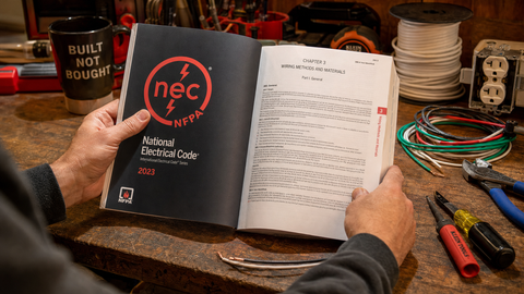
A listed box gives you the required enclosure for splices (NEC 300.15), the wire transition point (690.31), accessible labeling for rapid shutdown documentation, and a defensible answer for the inspector. NEC 690 and 705 installations live or die on these details.
5. Faster Installation Times
Crews that have the rhythm down land a junction box — flashed, sealed, wired, labeled — in 30 to 45 minutes. Compare that to building a multi-conduit penetration with individual flashings and a gutter transition, and the box pays for itself on labor before lunch.
Roof Material Compatibility
Roofing type decides whether a junction box is the right tool at all:
| Roof Material | Suitability | Notes from the Field |
|---|---|---|
| Asphalt shingles | Ideal — standard flashing integration | The design case; flashing laps under upslope courses |
| Composite/synthetic shingles | Excellent | Installs like asphalt; verify fastener compatibility |
| Cedar shake | Good with care | May require additional sealant and a flashing pan; shakes telegraph every bump |
| Clay/concrete tile | Specialized | Requires tile-specific flashing kits or deck-level mounts; never flash to the tile surface alone |
| Standing seam metal | Different hardware entirely | Use clamp-based or seam-mounted penetration solutions, not shingle-style flashing |
| Flat/membrane (TPO, EPDM) | Different hardware entirely | Use membrane-compatible penetration boots installed per the roofer's spec to preserve the roof warranty |
Asphalt shingles dominate U.S. residential housing stock, which is why the shingle-integrated junction box dominates residential solar. Three practical reasons: the flashing detail is a solved problem, the workable slope range (2.5:12 to 12:12 for the EZ Solar family) covers nearly every pitched roof you will encounter, and the deck underneath takes screws predictably.
EZ Solar Junction Box Specifications
The two models we stock and spec most often, from the manufacturer's published data:
| Specification | EZ Solar JB-1.2 | EZ Solar JB-1.XL |
|---|---|---|
| Maximum voltage | 1,000 V | 1,000 V |
| Maximum current | 80 A | 120 A |
| Allowable wire range | 14 AWG – 6 AWG | 14 AWG – 6 AWG |
| Enclosure rating | NEMA Type 3R | NEMA Type 3R |
| Roof slope range | 2.5:12 – 12:12 | 2.5:12 – 12:12 |
| Operating temperature | -35°C to +75°C | -35°C to +75°C |
| Certification | UL 1741 | UL 1741 |
| Recommended application | Systems up to ~10 kW | Systems ~10 kW – 20 kW+ |
Model selection follows circuit count and conductor size: a typical 8–12 kW residential system with three or four source circuits in 10 AWG fits the JB-1.2 with room to spare; once you are pulling six or more circuits or stepping up to 8 or 6 AWG for long runs, the XL's terminal capacity and 120A rating earn the modest price difference. When in doubt, count circuits, multiply by conductor bend radius, and buy the box your elbows will thank you for. Browse the EZ Solar line alongside alternatives from Soladeck and flashed-mount systems from Quick Mount PV and EcoFasten.
Code Requirements You Cannot Skip
| Code Reference | Requirement | Field Application |
|---|---|---|
| NEC 300.15 | Splices and terminations must be in boxes or enclosures | The junction box itself satisfies this — no mid-run attic splices |
| NEC 690.31 | PV wiring methods; PV Wire not permitted inside buildings | PV Wire to the box, THWN-2 in raceway from the box onward |
| NEC 690.31(G) | DC circuits inside buildings in metal raceway or MC cable | EMT or FMC from attic junction point to inverter |
| NEC 690.12 | Rapid shutdown of PV systems on buildings | Labels at the box documenting the RSD boundary and initiator |
| NEC 690.43 / Art. 250 | Equipment grounding and bonding | EGC sized per 250.122 lands on the box's ground terminal |
| NEC 110.3(B) | Install per listing and manufacturer's instructions | Slope limits, sealant spec, fastener spec are code, not suggestions |
| NEC 300.7(A) | Seal raceways where condensation/temperature differentials exist | Seal the conduit where it passes from hot attic to conditioned space |
Our NEC code compliance guide and the grounding and bonding guide go deeper on the 690/250 requirements. For conductor selection on both sides of the box, use the PV Wire vs. USE-2 vs. THHN guide.
Tools and Materials Checklist
| Item | Spec / Notes |
|---|---|
| Reciprocating saw + fine blade | For the deck cut; a jigsaw works on thin decking |
| Roofing knife / hook blades | Cutting shingle courses clean |
| Flat bar | Lifting shingle tabs without tearing them; break seals gently |
| Polyurethane or manufacturer-specified sealant | Use what the listing says — 110.3(B) makes it a code issue |
| Roofing nails or specified fasteners | Galvanized, per flashing instructions |
| Ice-and-water membrane (peel-and-stick) | Deck-level belt-and-suspenders around the penetration |
| Torque screwdriver | Terminal blocks have published torque values — use them |
| Strain reliefs / cord grips | Listed for the cable OD; Heyco-type fittings |
| Labels | Rapid shutdown, PV circuit identification per 690 and NEC 110.21 — see PV labels |
| Multimeter with DC voltage rating | Verify polarity and voltage before landing conductors |
| Fall protection | Harness, anchors, rope grab — OSHA 1926 Subpart M, no exceptions |
Step-by-Step: Installing a Rooftop Junction Box

Step 1: Plan the Location
Pick a spot as close to the array as practical — every foot of rooftop PV Wire is cost and exposure — centered between rafters, below the array's lower edge if the layout allows, and reachable from the attic side. Probe or scan the attic first: you are looking for a clear bay free of wiring, ducts, and blocking. Mark from below with a small test nail through the deck, then find it topside. Never locate the box in a valley, within 18 inches of a ridge cap transition, or anywhere water concentrates.
Step 2: Prepare the Roof Surface
Lift the shingle courses above and around the location with a flat bar, breaking the sealant strips gently. On cold days, warm the shingles with a heat gun on low or wait for sun — cold shingles crack, and cracked shingles are a leak you installed yourself. Remove the nails from the courses the flashing will slide under.
Step 3: Cut the Roof Penetration
Mark the opening per the template in the box's instructions and cut the deck with a reciprocating saw. Cut to the line — an oversized hole defeats the flashing's gasket geometry. Vacuum the sawdust out of the bay; you will be working through this hole in an hour.
Step 4: Install the Flashing Base
Apply a continuous bead of the specified sealant to the flashing flange's underside perimeter. Slide the flashing upslope under the loosened courses so the top edge laps beneath at least one full shingle course — water must always flow over, never under. Set the base into the opening, press to bed the sealant, and fasten per the instructions. Our habit: a peel-and-stick membrane collar around the penetration at deck level before the flashing goes on. Cheap insurance.
Step 5: Integrate with Surrounding Shingles
Re-lay the courses over the flashing flange, re-nail at the original points (never through the flashing's water channel), and seal any lifted tabs with a dab of roofing cement. Step back and read the water path with your eyes: every lap should shed downslope. If any shingle edge sits proud of the flashing, fix it now.
Step 6: Mount the Junction Box Enclosure
Fasten the enclosure to the base per the manufacturer's hardware — typically a gasketed bolt-down. Torque evenly in a cross pattern; an over-cranked corner warps the gasket and creates the leak path you just worked to prevent. Verify the cover opens and latches cleanly before you wire anything.
Step 7: Route and Connect Wiring
Bring the PV source circuits in through listed strain reliefs, leave a service loop, and land them on the terminal blocks — PV positive to its terminal, PV negative to its terminal, THWN-2 out the other side. Torque every terminal to the published value and mark your torqued lugs with a paint pen. Land the EGC on the ground terminal first, per NEC 250 discipline. Verify polarity with the meter before closing anything up; reversed polarity found now is embarrassing, found after energization is damaged equipment.
Step 8: Complete Interior Connections
From the box's underside, run raceway — EMT or listed flexible metal conduit for the DC run inside the building per NEC 690.31(G) — to the inverter or combiner location. Seal the raceway penetration where it crosses from hot attic to conditioned space per NEC 300.7(A); unsealed conduits pump moist attic air into walls and drip condensation into junction boxes. Pull your THWN-2, land it, and strap the raceway per Article 358.
Step 9: Final Inspection and Testing
With strings still open: verify voltage and polarity on every circuit, verify grounding continuity from rail to EGC terminal, verify every strain relief is snug, every terminal is torqued and paint-marked, and every required label is applied — rapid shutdown documentation, PV power source markings, and the directory of what lands where. Photograph the open box for the closeout package. Then close it, latch it, and walk the flashing one last time.
Common Mistakes to Avoid
Mistake #1: Improper Flashing Orientation
Flashing installed over the upslope shingles instead of under them — the single most common leak we get called about. Water runs downslope; every layer must lap like the shingles themselves. If you take one thing from this guide: the top of the flashing disappears under a full course of shingles.
Mistake #2: Insufficient Sealant Application
Dots of sealant instead of a continuous bead. Water finds the gap. Follow the manufacturer's pattern — it is engineered, and per NEC 110.3(B) it is the code-compliant installation.
Mistake #3: Overtightening Strain Reliefs
Crushing a strain relief until the cable jacket deforms or the fitting cracks. Snug to the specified torque or hand-tight plus a quarter-turn for unlisted values; the seal comes from the gland, not from brute force. Overtightened fittings crack a season later, and water follows the cable into the box.
Mistake #4: Inadequate Wire Service Loops
Conductors cut to exact length leave nothing for the future. Terminal blocks get replaced, circuits get re-landed, and the tech doing it in year nine needs slack. Leave a real loop — 6 inches minimum inside the box.
Mistake #5: Ignoring Temperature Ratings
Attics hit 150°F. Conductor ampacity derates hard at those temperatures — 90°C-rated THWN-2 is the floor, not the ceiling, and NEC 310.15 correction factors apply. The ampacity chart has the numbers; run them before you assume 10 AWG carries 30A up there. It does not.
Mistake #6: Skipping the Attic Inspection
Cutting blind into a deck and hitting a romex run, a duct, or a rafter turns a 40-minute task into a repair call. Ten minutes in the attic before the saw comes out is the best time investment on the job.
Best Practices for Long-Term Performance
Document everything. Photos of the open wired box, the flashing detail, and the label set go in the closeout package; they settle warranty arguments and help the next tech. Use only listed components — the box, the strain reliefs, the terminal blocks, the labels. A listed assembly is a system; one unlisted part breaks the chain. Maintain conductor separation inside the box — positive and negative dressed to opposite sides, service loops tidy, nothing chafing on a sharp edge. Plan for future access: do not bury the box under a future array expansion or a snow-slide path. And coordinate with the roof warranty — on newer roofs, have the roofer or an approved detail sign off; some shingle warranties care about third-party penetrations, and a two-page letter beats a denied claim.
Financial Benefits for Installers and Homeowners
For installers, the math is simple: a junction box penetration runs 30–45 minutes versus 2+ hours for a multi-conduit custom penetration, and callback risk drops with a listed, flashed assembly. On a crew-day rate, that is $150–$300 of labor per install plus reduced leak liability. For homeowners, the value is durability and serviceability — a dry attic, a system a technician can actually troubleshoot, and a clean inspection record that matters at resale. It is one of the few solar components where the cheap, fast, and correct answers are the same answer.
Inspection Day: What the AHJ Actually Looks At
Inspectors see hundreds of these boxes, and the good ones have a routine. Expect them to check: the flashing detail from a ladder or drone photo; the listing mark on the box and strain reliefs; terminal torque witness marks or a spot-check with a torque driver; the label set — rapid shutdown documentation, PV power source markings, circuit directory; grounding continuity at the EGC terminal; and the raceway transition on the attic side, including the NEC 300.7(A) condensation seal. The two failures we see called out most: missing or wrong rapid-shutdown labeling, and PV Wire extending past the box into the building — remember, PV Wire's listing does not cover in-building use, and the box exists precisely to make that transition. Have the manufacturer cut sheet and the permit card on site, keep the attic access lit and clear, and the inspection runs ten minutes.
Sizing the Box to the System
A final sizing note that saves retrofit pain: count your source circuits, then add one. Array expansions, string rebalancing after a shade remediation, and monitoring add-ons all consume terminal capacity, and a junction box with two spare terminals is worth far more than its price difference. If the design calls for 8 AWG homeruns on long runs — common when voltage drop matters on a big roof — verify the terminal blocks accept the wire size with the service loop bent; a 6 AWG THWN-2 conductor has a bend radius that fills a small box fast. That is the practical argument for the XL enclosure on anything over 10 kW: not the ampacity, the elbow room. And on multi-array roofs, one box per array plane keeps the circuit directory honest and the troubleshooting simple.
Weather Windows and Timing
Schedule these installs for dry, mild, low-wind days. Sealants have temperature windows — most specify application above roughly 40°F — shingles crack in the cold and scuff in extreme heat, and a gusty afternoon turns a flashing sheet into a sail. On multi-box installs, stage materials on the roof before the first cut and complete each penetration fully before opening the next; two open holes and one surprise squall is a story nobody wants to tell. We treat every penetration like the roof is ours, because for the length of the warranty, it effectively is.
Frequently Asked Questions
Do I need a junction box for rooftop solar, or can I use conduit penetrations?
Both are code-legal. Individual flashed conduit penetrations work, but a listed rooftop junction box consolidates circuits into one penetration, provides the required enclosure for the PV Wire to THWN-2 transition, and cuts install time substantially on multi-circuit arrays.
What size wire can a rooftop junction box accept?
The EZ Solar JB-1.2 and JB-1.XL both accept 14 AWG through 6 AWG conductors on their terminal blocks, with maximum ratings of 80A and 120A respectively at up to 1,000V. Always verify against the specific model's listing.
Will a rooftop junction box void my roof warranty?
Properly installed with integrated flashing, it generally will not — but some shingle manufacturers require notification or approved details for third-party penetrations. On newer roofs, coordinate with the roofer or get written confirmation before the install.
Can I install a rooftop junction box on a tile or metal roof?
Not with the standard shingle-integrated models. Tile roofs need tile-specific flashing kits or deck-level mounts; standing-seam metal roofs use clamp-based penetration solutions; membrane roofs need boots installed per the roofing manufacturer's spec.
Who can install a rooftop junction box — DIY or licensed only?
Licensing rules vary by jurisdiction, but rooftop PV electrical work typically requires a licensed electrician or solar contractor, permits, and inspection. The fall-protection requirements alone (OSHA 1926 Subpart M for workers) make this professional territory for most homeowners.
Related Products and Next Steps
Source the boxes, strain reliefs, labels, and raceway in one order: EZ Solar, Soladeck, boxes and covers, Staubli MC4 connectors, and PV Wire by the foot or spool. For the wider installation sequence, the solar installation guide and panel wiring basics connect this piece to the rest of the system.