Last Updated: April 2026 • Reviewed for NEC 2026 Compliance
Run conduit wrong and everything downstream of it fails — the pull, the inspection, eventually the insulation. Run it right and the wiring inside stays protected from impact, moisture, and heat for decades. We’ve bent and pulled thousands of feet of EMT and rigid on commercial buildouts, and the difference between a clean job and a red tag comes down to the handful of National Electrical Code (NEC) rules in this guide.
Here’s the whole workflow in order: picking the material, bending it, supporting it, and pulling wire through it — to code, the first time, from material selection through final termination.
⚡ Quick Answer
A conduit job that passes inspection comes down to four steps in order: (1) match the conduit type to the environment, (2) prep tools and site, (3) cut, bend, and mount with correct NEC support spacing, and (4) pull wire within fill limits (max 40% for 3+ conductors). Shortchange any one of them and you’ll hear about it from the inspector.
Key Takeaways
- Match conduit to environment — RMC where the pipe can get hit, EMT for protected indoor runs, PVC for wet and underground work.
- EMT and RMC get supported every 10 ft; PVC every 3 ft; everything within 3 ft of every box.
- No more than 360 degrees of total bends between pull points — four 90s is the hard ceiling on any run. >
- Three or more conductors can only fill 40% of the conduit’s cross-section. Overfill it and you’ll cook insulation and fail inspection. >
- A reamer is a safety tool, not a nicety — a sharp cut edge will skin the insulation off your conductors during the pull. >
- PVC goes 18" deep; RMC only needs 6". Every outdoor fitting and box has to be wet-location rated. >
- In-stock EMT, RMC, PVC conduit, and fittings with bundled kit pricing, nationwide delivery, and procurement support that speaks your language.
In This Guide
Choosing the Right Conduit for Your Project
Material choice is the first real decision on the job, and it’s not “whatever’s on the truck.” The conduit you pick sets your labor pace, your support spacing, your burial depth, and whether the run survives its environment. Get it right at the quote stage and the rest of the job gets easier.
On commercial work you’ll see Rigid Metal Conduit (RMC) where the pipe can get hit — loading docks, exposed mechanical rooms. Inside that same building, Electrical Metallic Tubing (EMT) is usually the right call: cheaper, lighter, faster to bend. Shift to residential or underground and PVC wins, because it doesn’t rust and it’s cheap.
Navigating Material Choices for Different Environments
The market backs up what we see at the counter. The global residential PVC conduit market was about USD 878 million in 2023 and is projected to grow at a CAGR of 8.1% through 2032. Lightweight, corrosion-proof, budget-friendly — that’s what most jobs actually need.
Conduit Material Comparison for Project Planning
Match the material to the environment and the budget. This table is the quick version:
| Conduit Type | Best Use Case | Key Advantage | Primary Consideration |
|---|---|---|---|
| RMC (Rigid Metal) | Exposed industrial, commercial, high-impact areas | Maximum physical protection; can serve as grounding conductor | Higher cost; more labor-intensive to install and bend |
| EMT (Electrical Metallic Tubing) | Indoor commercial and residential protected runs | Lightweight and easy to bend; cost-effective for large projects | Not suitable for high-impact areas or wet locations |
| IMC (Intermediate Metal) | Similar to RMC but lighter; most exposed locations | Strong protection with less weight and cost than RMC | Thinner walls than RMC; slightly less durable under extreme impact |
| PVC (Polyvinyl Chloride) | Underground burial, wet/damp, corrosive environments | Corrosion-resistant and inexpensive; easy to work with | Requires separate grounding wire; UV exposure causes degradation |
A Framework for Selection
Before ordering materials for your next project, run through this checklist:
- Moisture, chemicals, UV, temperature swings? PVC owns wet and underground work; galvanized rigid handles exposed outdoor runs.
- Can the run get hit — forklifts, carts, guys carrying ladders? RMC or IMC is the only answer for high-impact zones.
- EMT and PVC install far faster and cost less than rigid — the right call when the schedule and budget are tight.
- Confirm the material is NEC-approved for your installation type, and check local amendments — AHJs add their own rules.
Expert Tip for Procurement: On large commercial or utility-scale jobs, bundle the conduit order with panelboards, switchgear, and transformers. At PES Supply we consolidate freight and price kits as a package — one truck, one PO, less logistics headache. For another solid reference, this Electrical Conduit Installation Guide is worth a read.
Conduit Types Compared: EMT vs PVC vs Rigid vs FMC (NEC Quick Reference)
Every conduit type answers to its own NEC article, and inspectors cite chapter and verse when a run fails. This table is the fastest way to match material to application — including the burial ratings that decide what can legally go in a trench.
| Conduit Type | NEC Article | Best Uses | Burial Rating | Cost |
|---|---|---|---|---|
| EMT (thin-wall) | NEC 358 | Indoor exposed or concealed runs in dry locations — garages, basements, commercial interiors | Not rated for direct burial or severe corrosion; use compression fittings outdoors | $ |
| PVC Schedule 40 / 80 | NEC 352 | Underground feeders, wet and corrosive locations, concrete slabs | Direct burial at 18" cover (Table 300.5); Sch 80 required where exposed to physical damage | $ |
| Rigid Metal (RMC/GRC) | NEC 344 | Service masts, areas of severe physical damage, threaded runs | Direct burial with just 6" cover; heaviest-duty option | $$$ |
| IMC (intermediate) | NEC 342 | Lighter-weight alternative to rigid with similar protection | Direct burial at 6" cover | $$ |
| FMC (Greenfield) | NEC 348 | Short flexible whips to motors, fixtures, and equipment that vibrates | Dry locations only; use LFMC (NEC 350) for wet or outdoor runs | $$ |
Most residential jobs land in the same place: EMT above ground, PVC below it. A garage feeder or a heat-pump disconnect typically runs EMT or Schedule 80 PVC down the wall, transitions in a junction box, and goes underground in Schedule 40. Mixing types in one run is perfectly legal — each segment just follows its own article’s support, fill, and fitting rules.
Conduit Market Context
The demand for properly installed conduit keeps climbing with stricter codes and electrification. The global electrical conduit market was worth about USD 7.9 billion in 2024 and is projected to hit USD 15.14 billion by 2033 — driven by tighter NEC enforcement, commercial construction, solar and EV buildout, and fire-damage claims that make “optional” wiring protection a fantasy.

Your Essential Toolkit and Site Prep Checklist
Half of a clean conduit job happens before the first cut. Right tools on site, pathway cleared, boxes and straps marked. Skip the prep and you’ll pay for it in crooked runs, wasted sticks, and inspection callbacks.
The Toolkit You Actually Need
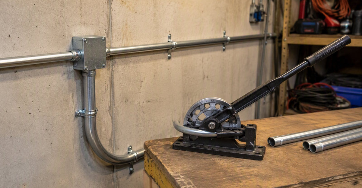
- A hand bender covers EMT up to 1-1/4". For RMC or bigger EMT on commercial work, bring a hydraulic bender — clean, kink-free bends without wrecking your shoulders. >
- A fine-tooth hacksaw is fine for a few cuts. Running volume? A portable band saw or a chop saw with a metal-cutting blade pays for itself by lunch. >
- This is a
- not optional. Every cut leaves a razor-sharp interior edge that will shred wire insulation during a pull. Always ream before pulling.
- Steel or fiberglass fish tape gets you through the bends; tie a pull string to the tape head and the conductors follow.
- Tape measure, torpedo level for tight spots, and a chalk line or laser level for long straight runs on walls and ceilings.
- A solid cordless drill with masonry, wood, and metal bits for straps and mounting hardware.
⚠️ Never Skip the Reamer
Skipping the ream is one of the most common mistakes we see. The razor edge a cut leaves inside the pipe shreds insulation as the wire comes through — and you might not find out until the circuit fails under load, years later. A reamer costs under $10. Use it.
Setting Up for Success: Site Preparation
Clear the pathway first — anything in the way now is a delay or a hazard later. Mark box, outlet, and strap locations straight off the drawings. Double-check every measurement with fitting thickness and bend radius in mind; miss those and the whole run lands wrong.
Pro Tip for Commercial Installers: Set up a bending station — a sheet of plywood on sawhorses gives the bender a flat, stable base. Bends come out consistent, and you’re not grinding galvanize off the pipe on rough concrete.
Mastering Conduit Bends and Offsets
Bending is where the craft shows. One bad bend can skin insulation on the pull, earn you a red tag, and force a tear-out of finished work. It’s the most expensive mistake on a conduit job — and it’s avoidable with technique and honest measuring.
The Three Foundational Bends
Learn these three and you’ll handle about 90% of what the field throws at you:
① Identify the obstacle or direction change required
↓
② Measure the required stub height, offset depth, or saddle height
↓
③ Select bend type: 90° Stub-Up / Offset / Saddle
↓
④ Calculate take-up / gain — subtract from target dimension
↓
⑤ Mark conduit with permanent marker (NOT pencil)
↓
⑥ Seat conduit correctly in bender shoe — apply even, steady pressure
↓
⑦ Verify bend angle and dimension — check for kinks before proceeding
- The most common bend — turning conduit from a wall into a box or down from a ceiling. Key calculation: subtract the bender's
- value from the desired stub height to find your mark location.
- Two equal, opposing bends (usually 30°) that shift the run sideways around an obstacle. The number that matters is the distance between the bends, figured from the offset depth.
- A three-bend “bridge” over a round obstruction like another pipe. Center mark goes dead over the obstacle, with two symmetrical marks for the flanking bends.
Common Bend Angles and Their Applications
The common bend angles, what each one is for, and how many bends each configuration takes:

Calculations and Avoiding Common Pitfalls
Two values run the bending math: take-up (how much pipe the bend eats) and gain (what you save by cutting the corner on a 90° instead of going square). Ignore either and nothing lines up at the boxes — the run lands long or short and you’re cutting threads at 4:45 on a Friday.
⚠️ Three Bending Mistakes That Fail Inspections
- >
- The #1 tell of amateur work. Too much pressure too fast, or the pipe seated wrong in the shoe. A kink constricts the raceway — it’s a code violation, and the stick goes in the scrap pile. >
- The NEC caps it at 360° between pull points — four 90s, period. Past that, nobody pulls wire through it without damage. >
- Dog legs are the little unintended wobbles in what should be a straight stick — usually from rushing. They look sloppy, add friction on the pull, and inspectors notice.
Field Tip: Never mark conduit in pencil — it wipes right off. Permanent marker. Repeating the same bend? Build a quick jig from scrap plywood: every stick comes out identical and your bending time drops by half on repeat runs.
Stub-Up and Offset Numbers Every Installer Memorizes
Two numbers do most of the bending work: the deduct (take-up) for a 90° stub-up, and the multiplier for offsets. Stub-up: measure the stub height from the end, add the deduct for your bender, mark, bend. Offset: multiply the offset depth by the multiplier for your angle — that’s the spacing between your two marks.
| Bend | Value | How to Use It |
|---|---|---|
| 1/2" EMT — 90° stub deduct | 5 inches | Mark stub height + 5", bend at the arrow |
| 3/4" EMT — 90° stub deduct | 6 inches | Mark stub height + 6", bend at the arrow |
| 1" EMT — 90° stub deduct | 8 inches | Mark stub height + 8", bend at the arrow |
| 22.5° offset multiplier | × 2.6 | Shrink allowance ≈ 1/4" per inch of offset depth |
| 30° offset multiplier | × 2.0 | Shrink allowance ≈ 3/16" per inch of offset depth |
| 45° offset multiplier | × 1.4 | Shrink allowance ≈ 3/8" per inch of offset depth |
Worked example: a 24-inch stub in 1/2" EMT. Mark at 24 + 5 = 29 inches from the end, bender arrow on the mark, bend to 90°. A 4-inch offset at 30°: marks 4 × 2.0 = 8 inches apart, 30° each, opposite directions. Burn a few scrap sticks practicing before you touch production material — a bundle of 1/2" EMT is cheap tuition.
Securely Mounting and Supporting Conduit Runs
Beautiful bends don’t matter if the run sags off the wall. Support is an NEC requirement, not a cosmetic choice — loose conduit stresses connectors, chafes wire over time, and it’s one of the first things an inspector scans. A well-supported run pulls easier, too.
NEC Support Spacing Requirements
Hard NEC rules, not suggestions. Spacing depends on the conduit type:
| Conduit Type | Max Support Spacing | Within 3 ft of Box Required? | Notes |
|---|---|---|---|
| EMT | Every 10 ft | Yes | Most common in commercial interiors |
| RMC / IMC | Every 10 ft | Yes | Larger diameters may have tighter requirements |
| PVC (½" – 1") | Every 3 ft | Yes | PVC sags significantly in heat — tighter spacing is critical |
| All Types — Near Boxes | Within 3 ft of every box | Yes — all types | Prevents mechanical stress on connectors and fittings |
NEC Support Spacing by Conduit Type
PVC needs 3× the straps of metal conduit — price that into material and labor on PVC-heavy jobs or you’ll eat it.

Selecting the Right Supports and Fasteners
Wood studs or joists: a one-hole or two-hole strap does the job. Mechanical rooms and parallel runs: step up to strut channel (Unistrut or equivalent), the industry standard for strong, adjustable, organized raceways anchored to structure. Rooftop work has its own rules — see our guide on installing a rooftop junction box for fastening that keeps the roof membrane intact.
Pro Tip: When in doubt, add a strap. It’s cheap insurance against sag, stressed connectors, and red tags. Chalk-line or laser the strap locations before you hang anything — ten minutes of prep buys a plumb, professional-looking run.
Pulling Wire and Finalizing Your Connections
The pull is where you find out how you did. A smooth pull means the layout was right — clean bends, honest fill math, enough lube. A brutal pull means something upstream went wrong: too many bends, a kink you missed, or an overfilled pipe.
Techniques for a Smooth Wire Pull
Run the fish tape through the empty conduit, tie on the bundle, pull back. Long runs or anything near the 360° limit need wire-pulling lubricant — without it, conductors grind the pipe walls and you’ll skin the insulation. Build a real pulling head: stagger the wire ends, strip back 6 inches, loop through the tape eye, and tape it into a smooth tapered nose that won’t hang up on couplings.
NEC Conduit Fill Limits
Fill limits get violated constantly, and the rules exist for two reasons: keeping insulation intact during the pull, and letting energized conductors shed heat. Pack wires too tight and insulation cooks — that’s how you get shorts and fires inside finished walls.
| Number of Conductors in Conduit | Maximum Allowable Fill (%) | NEC Reference |
|---|---|---|
| 1 Conductor | 53% | NEC Chapter 9, Table 1 |
| 2 Conductors | 31% | NEC Chapter 9, Table 1 |
| 3 or More Conductors | 40% | NEC Chapter 9, Table 1 |
Conduit Fill Limits by Number of Conductors
The drop from 53% (one conductor) to 31% (two) surprises everyone the first time. Check your fill against NEC Chapter 9, Table 1 before you pull — not after.

The 40% Rule Explained: It’s not arbitrary. The limit protects insulation on the pull and gives heat somewhere to go in service. Violate it and you’re looking at a failed inspection now, insulation breakdown later — and, worst case, a fire that shows up years after you’ve cashed the check.

Terminating Conduit and Making Final Connections
Terminate with the right fittings — EMT connectors for EMT, PVC terminal adapters for PVC. Metal fittings go wrench-tight: a loose one breaks the equipment grounding path and fails inspection on sight. Every conduit end inside a box gets a bushing so the cut edge can’t chew the wire. For enclosure picks, see our guide on choosing a Cantex electrical box for optimal safety.
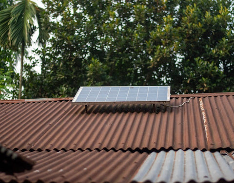
Conduit for Solar Installations: NEC 690 Essentials
Solar puts conduit through the worst conditions it will ever see — rooftop heat, decades of UV, and DC fault current that doesn’t behave like AC. Article 690 stacks its own rules on top of the raceway articles, and it changes which wire and which pipe belong where.
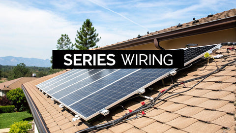
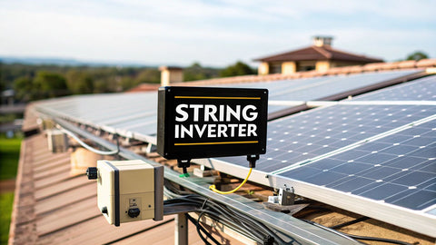
The conductors themselves are usually PV wire (photovoltaic wire) or USE-2 for exposed array wiring — both are sunlight-resistant and rated 90°C wet — transitioning to THHN/THWN-2 in conduit once the run enters the structure. NEC 690.31 governs wiring methods: PV source and output circuits may run exposed only where specifically permitted, and any rooftop run subject to physical damage needs raceway protection. Where PV circuits run inside a building, 690.31(G) pushes them into metal raceways (or metal-clad cable) for arc-fault containment — this is the rule that surprises installers moving from rooftop EMT to interior runs.
Three details separate a code-clean solar conduit job from a red tag:
- Expansion fittings on long PVC runs. PVC moves roughly 3–4 inches per 100 feet across seasonal temperature swings. NEC 352.44 requires expansion fittings where that movement exceeds 1/4 inch — which means nearly every straight rooftop PVC run over 8–10 feet.
- Temperature derating. Conduit on a sun-baked roof sees ambient temperatures 30–40°F above the air temperature. NEC 310.15 and 690.8 demand ampacity corrections that routinely force one wire size up on rooftop runs — a "12 AWG string" often becomes 10 AWG in conduit on the roof.
- Bonding metal raceways. EMT and rigid conduit carrying PV circuits must be bonded per NEC 250 and 690.43 — every coupling tight, every box bonded. That metal raceway often doubles as the equipment grounding conductor, but only if the continuity is there.
⚡ Solar Field Rule
On rooftops, use PVC only where it's shaded or protected — direct sun ages even UV-rated conduit, and Schedule 40 sags between supports above 90°F. Most pros run EMT with rain-tight compression fittings for exposed rooftop transitions and reserve PVC for the underground run to a ground-mount array. And never mix PV source circuits with AC branch circuits in the same raceway — 690.31(B) requires PV circuits to stay in their own conduit unless every conductor is rated for the maximum voltage present.
Common Conduit Installation Questions
Can you mix different types of conduit in the same run?
Yes — with UL-listed transition fittings. The classic case is PVC underground transitioning to EMT above grade. The right fitting keeps the raceway’s ground continuity and physical integrity, as the NEC requires. Never force-fit two conduit types without an approved transition connector.
What are the NEC rules for outdoor conduit installations?
Everything outdoors — fittings, boxes, supports — must be rated for wet or damp locations. Burial: PVC wants 18 inches of cover, RMC only 6. Outdoor receptacles need GFCI protection, and outdoor boxes need in-use weatherproof (“bubble”) covers so connections stay dry with cords plugged in.
When should you use flexible conduit?
FMC and liquidtight (LFMC) are for short final connections — motors and compressors that vibrate, tight spots where bending rigid isn’t practical, fixture whips. Don’t run flex on long exposed runs: less physical protection, more straps, and inspectors know the difference.
How do you run conduit underground correctly?
Dig to depth (18" for PVC, 6" for RMC), lay the run — usually PVC for the corrosion resistance — with large-radius sweeping elbows at direction changes. Never hard 90s underground. Call 811 before the trencher starts so buried utilities get marked, and backfill the first 6 inches with clean sand or fine soil so rocks can’t puncture the wall.
What is the maximum number of bends allowed in a single conduit run?
The NEC limits total bends to 360 degrees between pull points — four 90-degree bends, max. Past that, wire won’t pull without insulation damage, and it’s a code violation on its face.
What conduit depth is required for underground residential wiring?
NEC minimums: PVC — 18 inches; RMC — 6 inches; IMC — 6 inches. Local amendments can demand more, especially under driveways or traffic areas. Verify with your AHJ before you trench.
What are the basic steps of electrical conduit installation?
Plan the route and count your bends (360° max between pull points). Measure, cut, deburr every end. Bend, mount, and support per NEC spacing for your conduit type. Pull with lubricant. Terminate with the right fittings and bushings. Inspection comes before you close walls — leave the run accessible until it’s signed off.
What is the NEC 40% fill rule for conduit?
NEC Chapter 9, Table 1: 40% fill for three or more conductors, 53% for one, 31% for two. It protects insulation during the pull and lets heat escape in service. Annex C has the pre-computed conductor counts by conduit type and wire size — use it instead of doing the geometry on the tailgate.
EMT vs PVC conduit: which should I use?
EMT indoors, above ground, dry locations — light, cheap, bends easy. PVC (NEC 352) for underground, wet, and corrosive spots. The standard residential combo: EMT or Schedule 80 PVC on the wall, Schedule 40 PVC in the trench.
How deep do you bury electrical conduit?
Under NEC Table 300.5: PVC gets 18 inches of cover; RMC needs only 6 inches because of its physical strength. Under driveways or vehicle traffic, 24 inches. A 20-amp GFCI-protected 120V residential branch circuit can go as shallow as 12 inches.
Do solar panel installations require conduit?
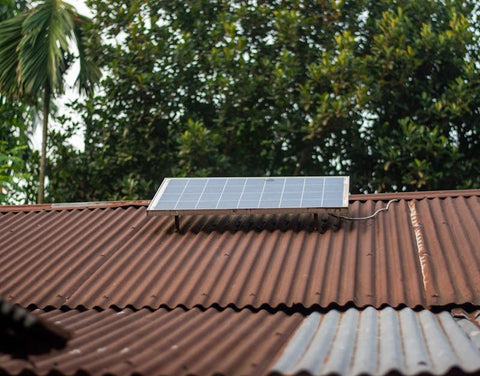
PV wire and USE-2 can run exposed on the array itself, but conduit is required wherever wiring faces physical damage, passes through the roof, or enters the building — NEC 690.31(G) pushes indoor PV circuits into metal raceway. Most residential jobs run EMT or PVC from the roof junction point down to the inverter.
How many bends are allowed in a conduit run?
360 degrees total between pull points — four 90° bends or any combination adding to 360°. More than that and you need a pull box. And fewer bends always pull easier: two 90s pull noticeably better than four.
Ready to Get Your Next Project Wired?
PES Supply stocks the conduit, fittings, and kits to do it right — pallets of EMT for a commercial buildout, PVC and fittings for a residential underground run, or a full bundled project kit. Fast quotes, bundled freight, nationwide delivery.
Request a Quote Today Shop Conduit and FittingsRelated Guides
- Size breakers correctly for the circuits inside your conduit runs >
- Weatherproof mounting for outdoor and rooftop conduit terminations >
- Selecting the right enclosure for conduit terminations >
- Panel sizing for the circuits your conduit feeds >
- Bulk conduit, fittings, and complete electrical project kits
About PES Supply
PES Supply is a nationwide electrical distributor offering conduit, fittings, wire, panelboards, switchgear, solar equipment, EV charging hardware, generators, and complete project kits. With a catalog of 50,000+ SKUs across 169 authorized brands and nationwide LTL freight delivery from our Louisville, Kentucky supply house, PES Supply serves contractors, EPCs, developers, and facility owners with fast delivery, bundled freight options, and code-aligned material sourcing.
Location: 1507 Portland Ave, Louisville, KY, United States | Phone: 1 888-876-0007 | Website: www.portlandiaelectric.supply
Article: How to Install Electrical Conduit: Step-by-Step NEC Guide for Installers, EPCs, and Project Managers
Category: Electrical Installation | Conduit | NEC Compliance | Commercial Electrical
Last Updated: April 2026 • Reviewed for NEC 2026 Compliance
Disclaimer: This guide is for informational and educational purposes. Always confirm compliance with the latest NEC edition, local code amendments, and the Authority Having Jurisdiction (AHJ) requirements for your specific project before beginning any electrical installation.
Related Resources:
- Best Solar Panels 2026 — Buyer's Guide
- EG4 vs Tesla Powerwall
- Qcells vs Trina vs JA
- Solar Inverter Buyer's Guide
- Solar Battery Buyer's Guide
- 5kW Solar Kit
- 10kW Solar + Battery Kit
- Off-Grid Cabin Kit
- EG4 Batteries
- Qcells Solar Panels
- Trina Solar
- JA Solar
- REC Solar
- Mission Solar
- Sol-Ark Inverters
- SolarEdge Inverters
- Generac PWRcell
Calculate how much storage you need with our battery sizing calculator.
Check solar incentives available in your state.
Use our free solar system calculator to size your array.
Check out our Solar Panel Comparison Tool. Check out our Inverter Sizing Calculator.
Calculate your solar payback and 25-year savings with our Solar ROI Calculator. Follow our complete DIY solar installation guide for step-by-step instructions. Keep your system running at peak performance with our Solar Maintenance Guide.
Related Resources
- Solar System Calculator
- Battery Sizing Calculator
- Solar Panel Comparison Tool
- Inverter Sizing Calculator
- Solar ROI Calculator
- Solar Installation Guide
- Solar Maintenance Guide
- Solar Permitting Guide
- Battery Installation Guide
- NEC Code Compliance Guide
- Solar Panel Mounting Guide
- Grounding & Bonding Guide
- Solar Incentives by State
- Pro Account — Wholesale Pricing
- PowerLink Network — Contractor Program
Related:
- Electric Vehicle (EV) Chargers — EV charger circuits that typically require dedicated conduit runs
- Complete Solar Kits — rooftop solar wiring that depends on properly installed conduit
- Solar Panel Kits Buyer’s Guide (2026) — plan conduit runs around a complete kit layout