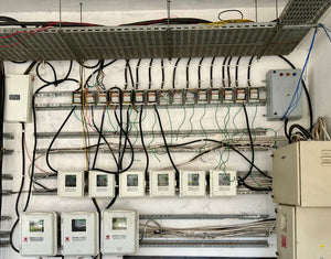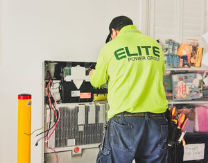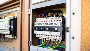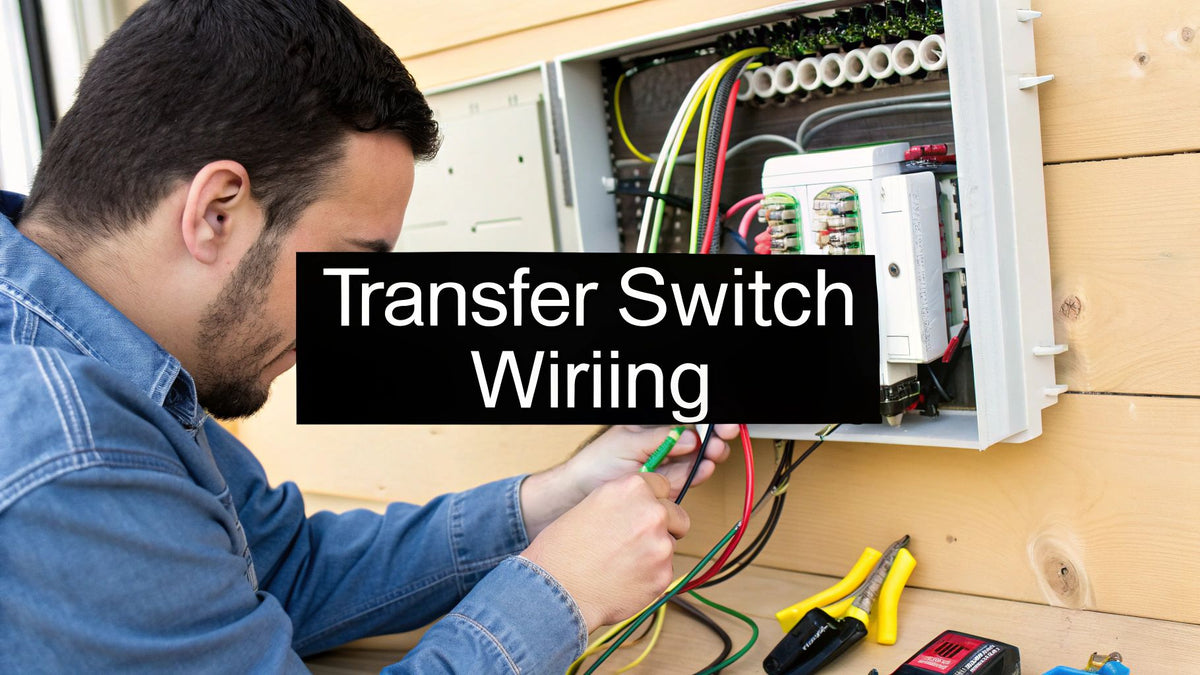
For the Electrical Contractor, Installer, or EPC: Proper transfer switch wiring is what separates a reliable backup power system from a dangerous, non-compliant hazard. This guide moves beyond theory to provide actionable, field-tested steps for safe, code-compliant installations that protect equipment, pass inspection, and ensure seamless power continuity for your clients. We'll cover the critical differences between manual and automatic setups, NEC grounding rules, and the commissioning process that proves your work is solid.
The Real-World Outcome: By following this guide, you will be able to confidently select, wire, and commission a transfer switch for any residential or commercial application, avoiding common pitfalls like backfeeding, improper grounding, and mismatched components that lead to costly rework and liability.
The Critical Role of Transfer Switch Connections
Think of a transfer switch as the heart of your backup power setup. For any facility manager, EPC, or electrical contractor, its wiring is more than just connecting circuits; it's about engineering a foolproof gateway that completely isolates your generator from the utility grid. This isolation is the fundamental principle that prevents catastrophic failures and keeps people safe.
The stakes couldn't be higher. A botched wiring job can lead to:
- Dangerous Backfeeding: Energizing downed utility lines creates a deadly hazard for technicians trying to restore power.
- Equipment Damage: If a generator connects to a live grid, it can instantly destroy the generator, the switch, and any appliances on the circuit.
- Code Violations: The National Electrical Code (NEC) governs every transfer switch installation. Failing to comply means failed inspections, expensive rework, and serious liability.
Manual vs. Automatic Wiring Considerations
Your choice between a Manual Transfer Switch (MTS) and an Automatic Transfer Switch (ATS) completely changes the game for wiring complexity and how the system responds in a blackout. An MTS is straightforward—someone has to physically throw a lever. It's a simple, hands-on solution.
An ATS, on the other hand, is the brains of the operation. It senses a power loss, automatically fires up the generator, and transfers the load without anyone lifting a finger. This seamless transition is essential for hospitals, data centers, and other critical facilities where downtime is not an option. Before diving into any wiring, a solid grasp of understanding electrical safety is the bedrock for preventing accidents and ensuring the system is reliable for years to come.
The market trend is clear: automation is king. Valued at USD 1.71 billion, the transfer switch market sees automatic switches from brands like Cummins and Generac accounting for over 60% of sales. Why? Because they eliminate human error and minimize downtime in critical sectors.
Key Differences in Manual vs Automatic Switch Wiring
When you're on the job, the wiring approach for an MTS is fundamentally different from an ATS. It's not just about flipping a switch versus letting a controller do the work; the complexity of control circuits, sensing lines, and overall footprint changes drastically. Here’s a quick breakdown for project planning.
| Wiring Consideration | Manual Transfer Switch (MTS) | Automatic Transfer Switch (ATS) |
|---|---|---|
| Circuit Complexity | Simple power conductors only (Grid, Load, Gen). No control wiring needed. | Complex. Requires power conductors plus multiple control and sensing circuits. |
| Control Wiring | None. Operation is purely mechanical. | Essential. Needs wiring for voltage sensing, generator start/stop signals, and load management. |
| Voltage Sensing | Not applicable. User determines when to switch. | Critical. Requires dedicated lines to monitor utility voltage and trigger the transfer. |
| Gen-Set Connection | Simple L1, L2, N, G connections from a portable inlet box or permanent generator. | Integrated two-wire start connection to the generator's control panel. |
| Physical Footprint | Smaller and more compact due to fewer internal components. | Larger and heavier to accommodate the control logic, solenoids, and motor mechanisms. |
| Best For | Residential homes, small businesses, and non-critical loads where manual operation is acceptable. | Hospitals, data centers, industrial plants, and any application where downtime is not an option. |
Expert Tip for Installers: Always double-check if you're working with a separately derived system (common for permanent standby generators) or a non-separately derived one (often found with portables). This determines if you need a switched neutral transfer switch to meet NEC 250.30. It's a detail that’s easy to miss but absolutely critical for safety. You can also learn more about the basics of what a transfer switch is in our detailed guide.
Ultimately, proper transfer switch wiring is about building a system that’s safe, compliant, and ready to perform under pressure. Whether you’re wiring a 100A manual switch for a house or a 1200A automatic switch for a commercial building, the core principles of isolation, correct sizing, and solid terminations never change. Getting these fundamentals right is the foundation of every successful backup power project.
Mapping Your Connections for Single and Three Phase Systems
The way you wire a transfer switch hinges entirely on the type of electrical service you're dealing with. Homes almost always run on single-phase power, while you'll find three-phase systems in just about any commercial or industrial building.
The core principle is identical for both—keep the utility and generator power completely separate—but the number of conductors and termination points changes significantly.
Single-Phase Setups: The Residential Go-To
For a typical home installation, say with a 200A manual transfer switch, you’re mostly working with four wires: two hots (L1, L2), a neutral, and a ground. Your job is to intercept the main feed coming into the service panel, run it through the transfer switch, and then direct the protected power out to a critical loads subpanel.
This subpanel is where you'll connect your "must-have" circuits—the refrigerator, furnace, well pump, and maybe a few lights. It’s a straightforward and solid way to manage backup power from a portable generator without attempting to power the entire house.
Tracing the Power Flow
Think of it like routing traffic. The path needs to be clean, logical, and with zero chance of a head-on collision.
Power comes in from the utility meter to your main panel, protected by the main breaker. From there, a properly sized feeder runs to the "Utility" or "Line" terminals on your transfer switch. A second, separate feeder runs from the "Generator" terminals over to your generator inlet box. Finally, the "Load" terminals send power out to your critical loads subpanel.
This diagram lays it all out.
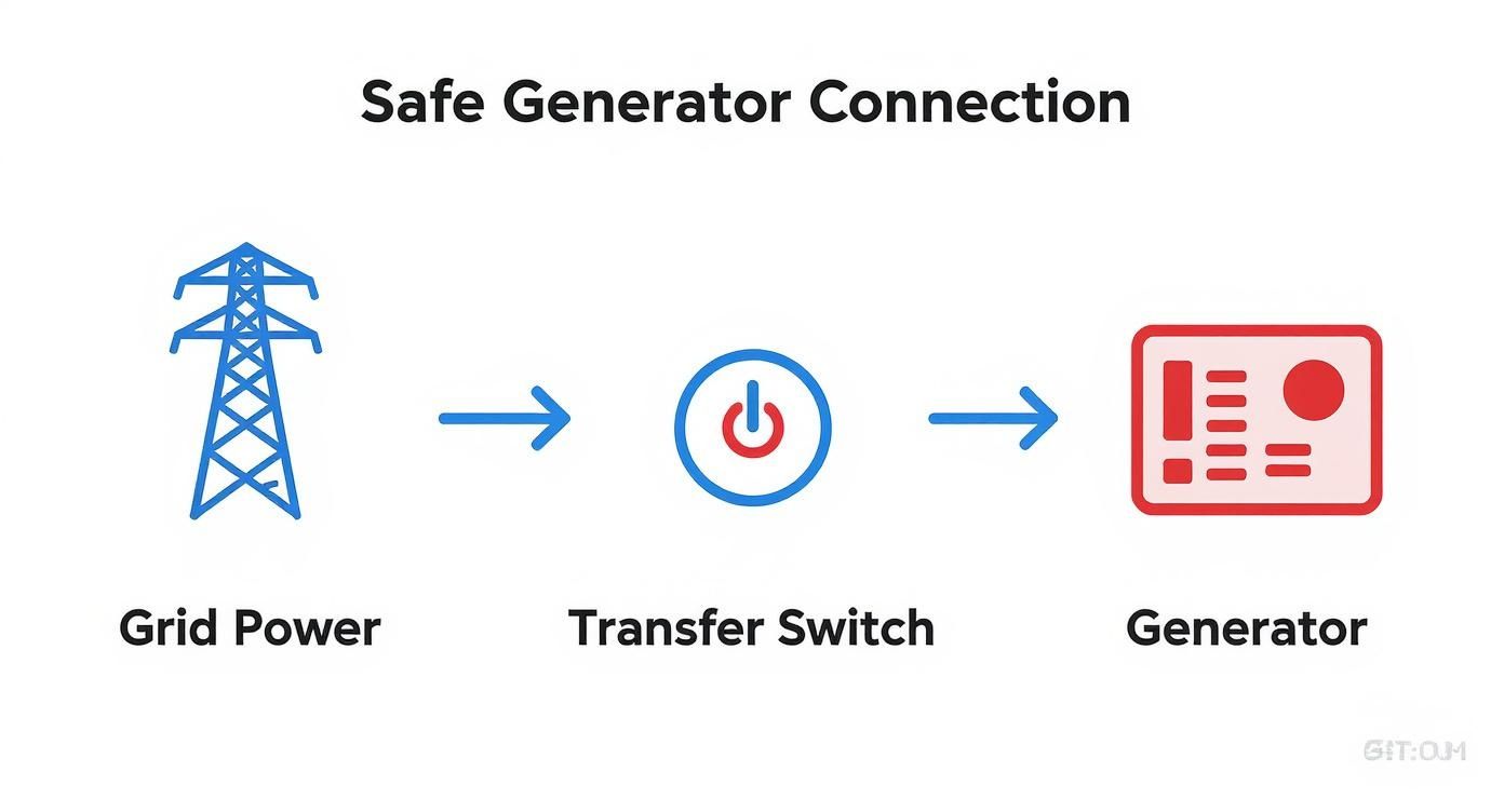
As you can see, the transfer switch acts as the gatekeeper, making it physically impossible for grid power and generator power to mix.
Three-Phase Wiring for Commercial Applications
Now, let's jump into the commercial world. Three-phase systems throw a third hot leg (L3) into the mix, which definitely adds a layer of complexity. Wiring a 400A Automatic Transfer Switch (ATS) for a small business with a permanent standby generator demands serious attention to detail, especially with phase rotation and control wiring.
Beyond the heavy-duty power conductors (L1, L2, L3, neutral, and ground), an ATS has a set of low-voltage control wires. These are the brains of the operation. They’re the communication link that tells the generator to fire up when the grid goes down and to shut off once utility power is stable again.
Guidance for Procurement Managers: When you're sourcing an ATS for a three-phase job, double-check that the switch is rated for the correct voltage (208V, 480V, etc.) and that its control logic is compatible with your specified generator's controller (e.g., a Cummins PowerCommand® controller). Mismatched components are a classic mistake that causes major commissioning delays. For a deeper dive, understanding three-phase power is essential.
In these bigger setups, the ATS is often powering an entire emergency panel dedicated to life-safety systems—emergency lights, fire alarms, and crucial IT gear. You've got to be meticulous. Terminating those thick-gauge conductors requires a torque wrench to hit precise specifications and prevent overheating. Every single connection—utility, generator, and load—has to be double-checked before you even think about energizing the system.
Your Field Checklist for Tools and Materials
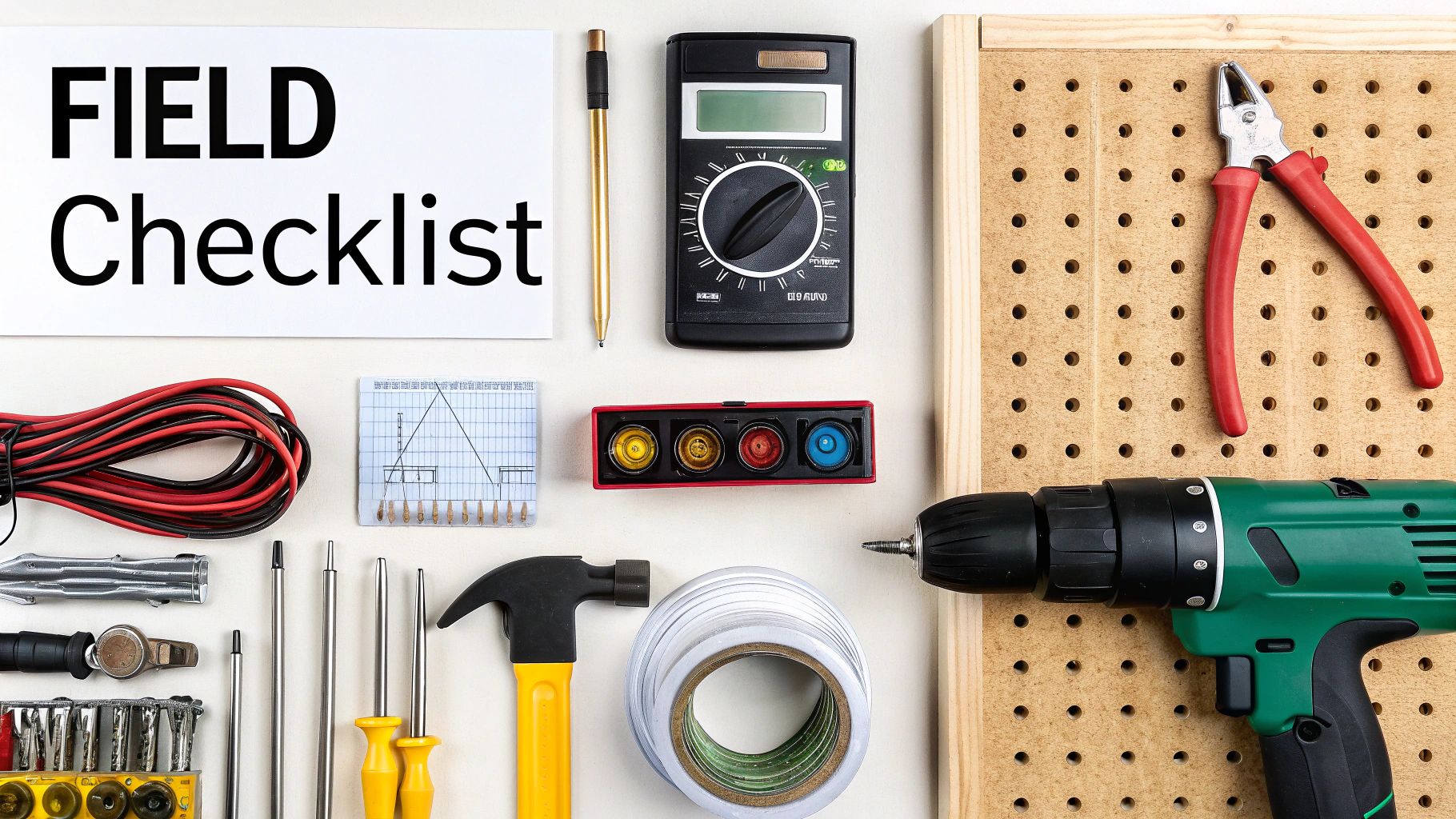
A clean, code-compliant transfer switch install doesn't just happen. It all starts with having every last tool and component on the truck before you even pull up to the job site. There's nothing worse than having to stop work for a missing lug or the right size wire nut—it kills momentum and project timelines.
This goes way beyond just having pliers and a screwdriver. A solid, safe job hinges on having the correctly specified materials for the load you’re connecting. No guesswork, no "close enough" substitutions.
Essential Power and Hand Tools
Before you touch a single wire, get your toolkit staged and ready. Having these items within arm's reach means no unnecessary trips back and forth, keeping your workflow smooth.
- Torque Screwdriver/Wrench: This is non-negotiable. NEC 110.14(D) requires it, and for good reason. Every terminal lug has a specific torque value to prevent overheating from a loose connection or damage from over-tightening.
- High-Quality Multimeter: You'll need it for everything—verifying voltages, checking continuity, and, most importantly, making absolutely sure the power is dead before you start working.
- Wire Strippers and Cable Cutters: Make sure they're sharp and sized for the gauge of wire you're using. A nicked conductor is a failure point waiting to happen.
- Conduit Bender and Cutter: Essential for running EMT or PVC conduit cleanly from the service panel and generator inlet to the transfer switch.
- Basic Hand Tools: A good set of insulated screwdrivers (Phillips and flathead), lineman's pliers, and a sharp utility knife are the foundation of your kit.
Critical Materials and Components
Getting the right materials is every bit as important as having the right tools. Using undersized wire or the wrong type of breaker isn't just a code violation—it's a serious fire hazard. Plan your bill of materials (BOM) before you start.
Pro Tip for Installers: When quoting a job, think about sourcing a complete kit. PES Supply offers bundled solutions, pairing a Cummins or Generac switch with the correctly sized breakers, lugs, and conduit fittings from the get-go. This ensures compatibility, eliminates field headaches, and streamlines the entire transfer switch wiring process.
- Conductors: Always use appropriately gauged THHN/THWN copper wire. For a standard 200A residential service, you'll most likely be pulling 2/0 AWG copper for your service conductors.
- Conduit: EMT is fine for indoor or protected runs, but you'll want liquid-tight or Schedule 80 PVC for anything outdoors or in exposed locations.
- Circuit Breakers: The breakers must be the correct type for the panel and sized to protect the feeder wires running to the transfer switch. No exceptions.
- Lugs and Connectors: Double-check that all your terminal lugs are rated for the wire size and type you’re using (e.g., copper/aluminum).
The industry is definitely moving forward. We're seeing more smart transfer switches with advanced diagnostic capabilities, especially in critical facilities where over 45% of new installations now feature smart systems. These can communicate directly with building management software to flag wiring faults instantly. You can learn more about these market trends to stay ahead of the game. Having the right tools on hand makes installing these advanced systems just as straightforward as the classic ones.
Wiring Your Transfer Switch from Panel to Generator
With all your parts and tools laid out, it's time to get into the heart of the project. This is where we physically connect the conductors that will bring your backup power system to life. Precision and a methodical approach are your best friends here. A safe, reliable job is a patient one.
Critical Pre-Installation Checks
Before a single wire is pulled, a few checks are absolutely mandatory. This isn’t just about being safe; it’s about setting yourself up for a clean, professional installation that will pass inspection.
First, kill the power. This means flipping the main breaker and then verifying with your multimeter that there is zero voltage at the main lugs. This double-check is non-negotiable—it's a fundamental rule of the trade.
Next, get the transfer switch enclosure mounted securely. Make sure it's level and plumb, anchored firmly to the wall per manufacturer specifications. A wobbly switch can cause connections to loosen over time from vibrations, creating a major fire hazard.
Finally, plan your conduit runs. Visualize the cleanest path from your main service panel, the generator inlet, and your critical load panel to the switch. Logical, well-planned runs look professional and make the wire pull much easier.
Step-by-Step Checklist: Routing and Connecting Conductors
Follow this sequence to ensure a logical and safe wiring process.
- Tie in the Utility Feed: Start by running the feeder conductors from a new two-pole breaker in your main service panel. Land these on the lugs marked "LINE" or "UTILITY" inside the transfer switch. These are usually the beefiest wires in the whole setup.
- Connect the Generator Input: Next up, pull the wires from your generator inlet box to the lugs marked "GENERATOR" or "GEN." This is the pathway that brings the backup power into your system. If you're still weighing options, our home backup power generator buying guide for outages breaks it all down.
- Wire the Load Output: Lastly, connect the wires from the "LOAD" terminals of the switch over to the main lugs of your critical load subpanel. These are the circuits that will stay on when the grid goes down.
Compliance Watchout: Before you get too far, ensure the main electrical panel can safely accommodate the new load. Sometimes, adding a transfer switch feeder requires a home electrical panel upgrade to handle the new breakers and load calculations per NEC Article 220. Don't skip this evaluation.
Torque Specifications and Wire Sizing
A loose connection is the number one enemy of any electrical installation. It creates resistance, which generates heat that can melt insulation and start a fire. This is exactly why NEC 110.14(D) mandates using a torque screwdriver or wrench.
Every lug has a specific torque value, usually printed on a sticker inside the enclosure. Hit that number. No guesswork.
Just as critical is using the right size wire. Undersized wires are a guaranteed overheating hazard. Always follow the NEC for proper sizing.
NEC Copper Wire Sizing Guide for Transfer Switches
This table provides general minimum wire gauges for copper conductors based on NEC 310.16 (75°C column). Always verify against local codes and the latest NEC edition.
| Transfer Switch Amperage | Minimum Copper Wire Gauge (AWG) |
|---|---|
| 30A | 10 AWG |
| 60A | 6 AWG |
| 100A | 3 AWG |
| 150A | 1/0 AWG |
| 200A | 3/0 AWG |
| 400A | 500 kcmil |
By following a deliberate workflow—pre-check, mount, route, and terminate to spec—you end up with an installation that’s not just working, but fundamentally safe and compliant.
Getting Grounding and Bonding Right
Messing up grounding and bonding is the fastest way to turn a backup power system into a serious hazard. This isn't a final checkbox. It's the absolute foundation of a safe transfer switch installation. Get this wrong, and you risk energizing the metal casing of your equipment, rendering breakers useless, and creating a genuine electrocution threat.
Grounding is your system’s connection to the earth, giving high-voltage surges from a lightning strike a safe path to dissipate. Bonding is about tying all non-current-carrying metal parts—conduit, enclosures, frames—together electrically. This ensures that if a hot wire ever touches the metal case, the fault current has a clear path back to the source, tripping the breaker instantly.
Switched Neutral vs. Solid Neutral
One of the biggest decisions you'll make is how to handle the neutral wire. Your choice between a switched neutral or a solid neutral transfer switch hinges entirely on whether your generator is a separately derived system.
-
Separately Derived System: Think permanent standby generators from brands like Cummins or Generac. These units have their own neutral-to-ground bond right at the generator. For these, you must use a 3-pole (single-phase) or 4-pole (three-phase) switch. This setup physically disconnects the utility neutral when the generator kicks on, preventing dangerous parallel paths and ground fault problems.
-
Non-Separately Derived System: This is your typical portable generator. Its neutral isn't bonded to the frame. For these, the neutral connection to the main service panel must stay intact. You'll use a transfer switch with a solid, unbroken neutral bar to maintain that path.
Critical Mistake to Avoid: Always, always check the generator's configuration before you even order the switch. Pairing a solid neutral switch with a separately derived generator is a major violation of NEC 250.30. It can disable your ground-fault protection and create a lethal shock hazard.
Meeting NEC Grounding Requirements
The National Electrical Code is clear about grounding. Any permanent setup needs a proper grounding electrode system—usually one or more ground rods driven into the earth and connected to your main panel with a correctly sized copper wire.
The transfer switch enclosure must be tied into this system. You’ll run a bonding jumper (a green or bare copper wire) from the ground bar in the main panel over to the ground bar in the transfer switch. This bonds the metal box to the system ground, completing that critical safety path for fault current.
This isn't just a local code, either. The global push for grid stability has put a spotlight on these safety standards. For instance, some market analyses show over 60% of new solar plants now use transfer switch logic to handle grid instability, all built on strict grounding protocols. You can discover more insights about these international standards at GMI Insights.
For a permanent standby generator, it will also need its own grounding electrode, bonded directly to the generator's frame. This is what officially makes it a separately derived system, and it's why switching the neutral is non-negotiable.
Commissioning Your System for a Final Inspection
Getting the switch mounted and wired is only half the battle. A system isn't finished until it's been run through a full commissioning process. This is the final shakedown—the proof that your transfer switch wiring is safe, reliable, and ready to pass inspection with flying colors.
Cutting corners here is a classic rookie mistake. This is your chance to find a minor glitch before it becomes a major callback. Think of it as creating the documented proof of a professional, by-the-book installation.
Pre-Power Up Inspections
Before flipping a breaker, do a thorough "cold check." This is your last chance to catch any wiring mistakes while the system is de-energized. Finding a problem now is a simple fix; finding it under load can be a disaster.
Your pre-power checklist should be second nature:
- Torque, Then Torque Again: Grab your torque wrench and hit every single terminal lug one more time—utility, generator, and load. Wires can settle, and what was tight yesterday might have play today. This second pass ensures every connection is rock-solid.
- Give the Conductors a Once-Over: Eyeball all wiring. Look for pinched insulation, ensure conductors are routed cleanly, and check for stray copper strands near opposing terminals.
- Check Phase Rotation (For Three-Phase): This is non-negotiable on commercial jobs. Getting the phase rotation wrong can make three-phase motors in HVAC units or machinery spin backward, causing catastrophic failure. Use a phase rotation meter on both the utility and generator inputs to confirm they are identical.
Live System Testing Protocol
Once all cold checks are signed off, it's time to go live. This is a controlled, deliberate simulation of a power failure designed to test every function of the transfer switch.
A Note for the Project Manager: Document everything during this live test. Record voltage readings, transfer times, and system responses. This commissioning report is a critical part of your project closeout package. It provides the client with proof of a successful job and is exactly what the electrical inspector wants to see.
Start by simulating an outage—kill the main breaker feeding the transfer switch's utility side. The system should spring to life.
- Confirm the transfer sequence. For an Automatic Transfer Switch (ATS), the generator should start. The switch will wait for a pre-set time delay for the generator to stabilize, then you'll hear the "clunk" as it transfers the load. For a manual switch, this is when you'd walk the owner through the transfer steps.
- Verify your voltage and frequency. With the building on generator power, use your multimeter at the load panel. You want to see stable voltage (a solid 120/240V for single-phase) and a steady frequency right at 60 Hz.
- Test the return to normal. Flip the utility main breaker back on. A properly configured ATS will sense the grid is stable, transfer the load back to utility, and then run the generator through its cool-down cycle before shutting down.
Questions We Hear All the Time About Transfer Switch Wiring
After years in the field, you start to hear the same questions pop up. When it comes to transfer switch wiring, installers and facility managers often run into the same handful of issues. Let's cut through the noise and get you some straight answers.
Do I Really Need a Switched Neutral Transfer Switch?
Here’s the deal: you absolutely need a switched neutral transfer switch if you're dealing with a separately derived system. Think permanent standby generators—the kind with their own neutral-to-ground bond already in place. A switched neutral is non-negotiable here; it prevents dangerous parallel neutral currents from flowing back where they shouldn’t. It's a critical safety and code issue defined by NEC 250.30.
On the other hand, for non-separately derived systems, a solid neutral switch is your go-to. This is common with portable generators where the neutral isn't bonded at the unit itself.
A Tip from the Trenches: Before a single tool comes out of the truck, confirm the generator's bonding configuration. Getting this wrong is one of the most common—and most hazardous—mistakes we see.
What's the Real Difference: Interlock Kit vs. Transfer Switch?
An interlock kit is basically a mechanical gatekeeper. It's a simple metal slider that physically stops the main breaker and the generator backfeed breaker from being on simultaneously. It's a low-cost solution for some residential jobs, but remember, it’s a fully manual setup and often doesn't switch the neutral conductor, which may not meet code depending on the generator.
A proper transfer switch is a whole different beast. It's a purpose-built device that completely isolates your circuits from one power source before connecting to the other. This break-before-make action offers a far safer, more reliable transfer. It can be automated and is typically required by code for any life-safety or critical systems.
Can I Get Away With Using Aluminum Wire?
The NEC technically allows aluminum wire if it’s sized correctly for the load, but let's be honest: copper is almost always the better choice. You just can't beat its conductivity and resistance to corrosion at the termination points.
If the job specs force your hand and you must use aluminum, do it by the book. First, check that the transfer switch lugs are dual-rated—look for the AL/CU stamp. Second, you must apply an antioxidant compound to the stripped wires and torque the lugs down to the manufacturer's exact specifications. No shortcuts here, or you’re asking for a loose, oxidized connection down the road.
Whether you’re hooking up a small manual switch for a home or a complex ATS for a commercial building, the quality of your components makes all the difference. PES Supply stocks a full lineup of code-compliant transfer switches, conductors, and all the accessories you need to do the job safely and professionally. Request a Bulk Quote today and let's get your next project wired right.
Related Resources:
- Best Solar Panels 2026 — Buyer's Guide
- EG4 vs Tesla Powerwall
- Qcells vs Trina vs JA
- Solar Inverter Buyer's Guide
- Solar Battery Buyer's Guide
- 5kW Solar Kit
- 10kW Solar + Battery Kit
- Off-Grid Cabin Kit
- EG4 Batteries
- Qcells Solar Panels
- Trina Solar
- JA Solar
- REC Solar
- Mission Solar
- Sol-Ark Inverters
- SolarEdge Inverters
- Generac PWRcell
Calculate how much storage you need with our battery sizing calculator.
Check solar incentives available in your state.
Use our free solar system calculator to size your array.
Check out our Solar Panel Comparison Tool. Check out our Inverter Sizing Calculator.
Calculate your solar payback and 25-year savings with our Solar ROI Calculator. Follow our complete DIY solar installation guide for step-by-step instructions. Keep your system running at peak performance with our Solar Maintenance Guide.
Related Resources
- Solar System Calculator
- Battery Sizing Calculator
- Solar Panel Comparison Tool
- Inverter Sizing Calculator
- Solar ROI Calculator
- Solar Installation Guide
- Solar Maintenance Guide
- Solar Permitting Guide
- Battery Installation Guide
- NEC Code Compliance Guide
- Solar Panel Mounting Guide
- Grounding & Bonding Guide
- Solar Incentives by State
- Pro Account — Wholesale Pricing
- PowerLink Network — Contractor Program