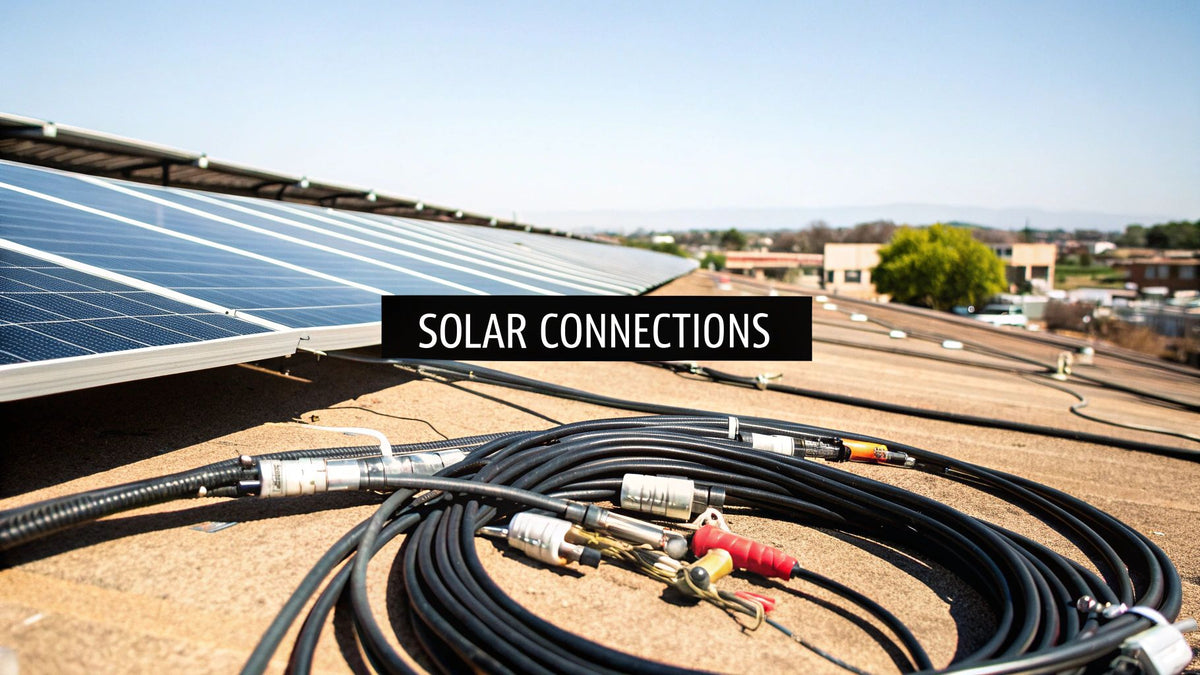
I have pulled, crimped, clipped, and troubleshot solar wire on everything from a 6 kW garage array to a 2 MW ground mount, and the lesson cost me real money early on: solar cables and connectors decide whether a system quietly prints kilowatt-hours for 25 years or quietly burns margin in truck rolls and hot connections. Panels get the glory on the quote sheet. The wire and the connectors do the work.
This is the guide I wish someone had handed me on my first commercial job. We will walk the cable types the NEC actually allows and where each belongs, the connector hardware that survives real weather, wire sizing math that passes inspection on the first submission, installation habits that prevent callbacks, and a procurement approach that keeps compliant material on the truck. Every table here is one my crews use in the field—bookmark it, print it, laminate it.
Why Your Cable and Connector Choice Is So Critical

While panels and inverters get the spotlight, any seasoned solar professional knows that a project's reliability hinges on its wiring. For installers on the roof, EPCs managing multi-megawatt sites, and developers securing financing, skimping on solar cables and connectors is a guaranteed route to expensive, and often dangerous, failures. These highly engineered components form the backbone of your system's performance and long-term bankability. Trying to value-engineer wiring is a classic error that can quickly turn a minor upfront saving into a massive operational liability, jeopardizing the entire asset.
The Real-World Cost of Cutting Corners
Specifying the wrong cable, using a non-compliant connector, or rushing installation leads to tangible, high-stakes problems in the field. These are not hypotheticals; they are the common pitfalls that cause project delays, create safety hazards, and erode investor confidence.
Here’s what you’re really risking:
- Failed Inspections and Project Delays: An inspector finding non-UL listed materials or improper workmanship is the fastest way to get a red tag. This means costly rework, blown timelines, and liquidated damages.
- Serious Safety Hazards: A poorly crimped connector or an underrated cable creates a point of high resistance. This "hot spot" can lead to an arc fault—a primary cause of fires in PV installations and a significant liability.
- Lost Power and Lost Revenue: Undersized cables act as a bottleneck, causing excessive voltage drop before power reaches the inverter. Over a system's 25+ year lifespan, that lost energy translates directly to lost revenue.
- Voided Warranties and Denied Insurance: Mating connectors from different manufacturers or using non-certified components is a surefire way to void equipment warranties. In the event of a failure, it can also be grounds for an insurance claim denial.
For Procurement Managers: The marginal saving from sourcing uncertified or lower-grade cables is dwarfed by the cost of rework, the liability from a fire, or the long-term underperformance of a multi-million dollar asset. It’s a high-risk gamble that never pays off.
For Developers: Ensuring your EPC uses compliant, high-quality wiring is critical for de-risking the project and satisfying investor due diligence. Specify genuine, UL-listed components in your procurement standards.
The market for these components is exploding, reflecting their critical role. The global cables and connectors market statistics show a valuation of USD 108 billion in 2024, projected to hit USD 157.4 billion by 2033. This growth is driven by the global transition to renewables, which demands specialized, high-performance wiring to ensure asset reliability.
Navigating Solar Cable Types and Specifications
Selecting the correct solar cable is far more than matching a gauge size. It’s about choosing a critical component engineered to survive decades of extreme UV exposure, temperature swings, and moisture while safely delivering maximum power. For any professional, understanding the nuances between cable types is fundamental to building a safe, compliant, and bankable solar asset. Getting it right ensures decades of reliable operation; getting it wrong leads to costly rework, failed inspections, and severe safety risks.
The Big Three: Core Solar Cable Types Explained
The National Electrical Code (NEC) provides clear directives on which cables are permitted for specific applications within a PV system. On most commercial and utility-scale job sites, you'll encounter three main types: PV Wire, USE-2, and TC-ER. While they may appear similar, their construction, ratings, and approved uses are fundamentally different.
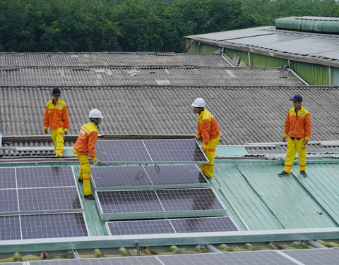
This overview illustrates how these common solar cables are deployed in a typical project.

Each cable is engineered for a specific function, dictated by its material properties and UL listings.
- PV Wire (Photovoltaic Wire): This is the industry standard for any exposed wiring, such as module-to-module "jumper" connections. Its robust, cross-linked polyethylene (XLPE) insulation is designed for maximum resistance to sunlight, moisture, and flame. It is the only cable type permitted by the NEC for use in ungrounded PV arrays.
- USE-2 (Underground Service Entrance): Also sunlight-resistant and suitable for outdoor use in grounded arrays, USE-2 typically has a thinner jacket than PV Wire. It's often specified for home runs protected within conduit, where it is shielded from physical damage.
- TC-ER (Tray Cable-Exposed Run): A significant labor and material saver on large commercial projects. Designed for use in cable trays, its key advantage is the "ER" rating, which permits it to be run exposed between the end of the tray and the connected equipment without conduit (subject to specific NEC rules).
A Practical Look at Common Cable Types
This table provides a real-world comparison to guide selection for your specific application.
| Cable Type | Primary Use Case (NEC) | Insulation/Jacket Material | Voltage Rating | Pro Tip for Installers |
|---|---|---|---|---|
| PV Wire | Exposed module-to-module connections and string wiring in both grounded and ungrounded arrays. | Thick XLPE (Cross-Linked Polyethylene) for maximum UV and weather resistance. | 600V, 1000V, 2000V | The only choice for module jumpers and exposed wiring on ungrounded systems. Its durability is worth the slightly higher cost. |
| USE-2 | Underground feeders and branch circuits. Often used for home runs inside conduit on grounded arrays. | XLPE or EPR (Ethylene Propylene Rubber), generally less thick than PV Wire. | 600V | A cost-effective option for protected runs. Never use it for exposed module interconnects—it's not rated for that kind of abuse. |
| TC-ER | Runs in cable trays or exposed runs from tray to equipment. Ideal for commercial/utility scale. | PVC/Nylon or XLPE. Must be rated for exposed runs. | 600V, 1000V | Check NEC 336.10(7) carefully. Using TC-ER correctly can eliminate hundreds of feet of conduit, saving big on time and budget. |
Ultimately, your choice is dictated by the installation environment and code requirements. Matching the cable to the application isn't just best practice—it's mandatory for a safe and durable system.
What’s Inside Matters: Conductors And Insulation
A cable's performance is determined by two core components: the conductor carrying the current and the insulation protecting it.
For solar applications, the conductor is almost exclusively copper. While aluminum is lighter, copper offers superior conductivity and significantly better corrosion resistance over the asset's lifespan. Tinned copper is the premium choice, adding a crucial layer of defense against moisture—a non-negotiable feature for a system expected to perform for 25 years or more.
The insulation is where advanced material science comes into play. Modern solar cables and connectors utilize XLPE for its exceptional toughness. It resists melting or becoming brittle under the extreme heat found on a rooftop and withstands abrasion and constant UV degradation.
Compliance Watchout: Always verify the temperature rating printed on the cable jacket. A 90°C wet/dry rating is the minimum standard for any wiring exposed to the elements. The ambient temperature under a solar panel can easily exceed this, causing lower-rated cable insulation to fail, creating a code violation and a severe fire hazard.
Decoding Voltage Ratings
Solar cables are available with several DC voltage ratings, typically 600V, 1000V, or 2000V. The rule is absolute: the cable's voltage rating must be equal to or greater than the PV system's maximum system voltage (Vmax).
- 600V: Once common in residential systems, the industry is largely moving to higher, more efficient voltages. We cover the specifics in our guide to 600V photovoltaic wire options.
- 1000V & 1500V: These are the new standards for commercial and utility-scale projects. Higher system voltages allow for longer series strings, reducing the number of combiner boxes, amount of wire, and overall balance-of-system (BOS) costs.
- 2000V: Primarily used in large-scale utility projects, 2000V systems maximize efficiency and drive down the levelized cost of energy (LCOE) on a massive scale.
Selecting Connectors That Ensure System Reliability
A solar cable is only as reliable as its connection points. A loose, poorly crimped, or improperly sealed connector is one of the most common points of failure in a PV system—a small component with outsized responsibility for system safety and performance. These connections are ground zero for arc faults, moisture intrusion, and high-resistance hotspots. For installers, EPCs, and asset owners, compromising on connector quality is a direct path to troubleshooting nightmares, safety liabilities, and underperforming assets. A secure, low-resistance connection is paramount.
The Anatomy of a Reliable Connection
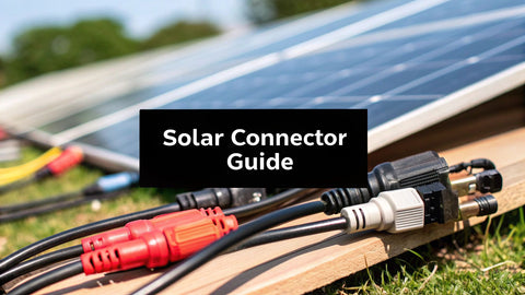
The undisputed industry standard for solar connectors is the MC4 style. Its design is ubiquitous for good reason—it’s field-proven and reliable. However, not all "MC4-compatible" connectors are created equal. Understanding the components of a high-quality connector is the first step to ensuring system integrity.
A reliable connector is a system of precision-engineered parts:
- The Metal Pin: This is where current flows. It must be crimped to the stripped cable using a calibrated tool to create a solid, gas-tight mechanical and electrical bond.
- The Gland Seal: At the rear of the connector, a rubber or silicone gasket compresses onto the cable jacket. This creates a weather-tight, IP67/IP68-rated seal that prevents moisture ingress.
- The Secure Mating Mechanism: The male and female housings must lock together with an audible and tactile "click." This locking feature ensures the connection will not separate due to thermal cycling or wind-induced vibration.
When all three elements are correct, the connection is built to last the 25+ year lifespan of the solar array. The failure of even one element compromises the entire string.
Why Genuine Stäubli MC4s Stand Apart
Stäubli is the original inventor of the MC4 connector, and their products remain the benchmark for quality and reliability. While many brands manufacture "MC4-compatible" versions, experienced professionals recognize the tangible differences.
Genuine Stäubli connectors use superior materials, including high-quality copper alloy contacts and advanced polymers for the housing that resist UV degradation and extreme temperatures far better than generic alternatives. They also carry stringent UL listings that guarantee performance and safety—but only when used as a complete, matched male/female system.
Compliance Watchout for All Installers: Cross-mating connectors from different manufacturers is a direct violation of the National Electrical Code (NEC 690.33(C)) and manufacturer warranties. Even if they physically click together, microscopic differences in tolerances can create a poor seal, leading to moisture ingress and dangerous arc faults. Always use the same brand for both male and female ends to ensure a compliant, safe, and warrantied connection.
The global demand for these critical components is surging. The photovoltaic solar connectors market growth is projected to expand from USD 849.26 million in 2024 to USD 2,459.16 million by 2032. This growth is driven by the urgent need to mitigate connector failures, which have caused significant revenue losses and pushed the industry toward higher-quality, certified components.
The Case for Factory-Terminated Cables
On large-scale projects, minimizing field labor and eliminating sources of error is critical for project bankability. This is where factory-terminated cables—also known as "whips" or "jumpers"—offer a decisive advantage. Instead of installers assembling thousands of connectors on-site, these cables arrive with connectors perfectly attached in a controlled factory environment. This process uses automated equipment to ensure every crimp is precise and every seal is tight, dramatically reducing the risk of human error.
Benefits for EPCs and Developers:
- Reduced Labor Costs: Dramatically accelerates module interconnection time on site.
- Improved Quality Control: Eliminates inconsistent field crimps, a notorious source of long-term failures.
- Enhanced Bankability: Lowers operational risk (O&M), making the project more attractive to financiers.
- Simplified Procurement: Consolidates multiple SKUs (bulk cable, male connectors, female connectors) into a single finished component.
By specifying factory terminations, project managers can guarantee that every connection point meets the highest quality standards, saving valuable time and boosting system reliability.
Mastering Wire Sizing and Voltage Drop
Proper wire sizing is not a mere technical detail—it's foundational to a safe, high-performing, and profitable solar project. For system designers and engineers, this is a non-negotiable skill. Undersizing a wire creates a fire hazard, guarantees a code violation, and throttles system output. The process is governed by two principles: ensuring the wire's ampacity is sufficient for the maximum current and keeping voltage drop to an absolute minimum. Excessive voltage drop is lost energy, which translates directly to lost revenue over the life of the asset.
The Core Principles of Sizing and Voltage Drop
Wire sizing is a balancing act governed by the National Electrical Code (NEC). The process involves calculating the wire's required ampacity (current-carrying capacity after all adjustments) and then confirming that the chosen wire gauge does not result in excessive voltage drop over the circuit's length.
The physics are straightforward: a thicker wire (lower American Wire Gauge or AWG number) has less resistance. This allows it to carry more current without overheating and ensures less energy is lost as heat. A 10 AWG wire, for instance, is larger and has a higher ampacity than a 12 AWG wire.
For Procurement and Development: Value-engineering copper is almost always a losing proposition. A slightly larger gauge wire may have a higher initial cost, but it pays for itself many times over in increased energy yield. On a utility-scale project, allowing voltage drop to creep up by just 1-2% can translate into tens of thousands of dollars in lost revenue over 25 years.
Calculations must account for real-world conditions. Wires in a hot conduit on a sun-drenched commercial roof operate at much higher temperatures than the ambient air, which significantly reduces their safe ampacity. The NEC mandates specific correction factors for both ambient temperature and conduit fill (number of conductors) to address this reality. Ignoring these factors is a direct code violation.
A Real-World Sizing Example
Let's calculate the minimum wire size for a typical utility-scale string to keep voltage drop within an acceptable range.
System Parameters:
- Maximum System Voltage: 1500 VDC
- String Current (Imp): 13 Amps
- One-Way Wire Length: 500 feet
- Target Voltage Drop: Less than 2%
- Conductor: Copper PV Wire
The standard formula for voltage drop is:
Voltage Drop = (2 x L x K x I) / CM
- L = One-way length of the wire in feet (500)
- K = Resistivity of the conductor (12.9 for copper)
- I = Current in amps (13)
- CM = Circular Mils of the conductor (from NEC Chapter 9, Table 8)
Let's test a 12 AWG copper wire to see if it meets the criteria.
Example Voltage Drop Calculation for 12 AWG Copper PV Wire
| Parameter | Value/Formula | Result | Notes |
|---|---|---|---|
| Circular Mils (CM) | From NEC Table 8 | 6,530 CM | This is the standard cross-sectional area for 12 AWG wire. |
| Voltage Drop (VD) | (2 * 500 * 12.9 * 13) / 6530 | 25.7 Volts | This is the total voltage lost over the 1,000-foot round trip. |
| Percentage Drop | (VD / System Voltage) * 100 | (25.7V / 1500V) * 100 | 1.71% |
| Conclusion | 1.71% < 2.0% Target | Pass | The 12 AWG wire meets our strict voltage drop requirement. |
This calculation shows that 12 AWG wire keeps voltage drop under our 2% target. However, this is only half the process. You must still apply all relevant NEC correction factors for temperature and conduit fill to ensure the wire's final ampacity is sufficient for the site-specific operating conditions.
Critical Mistakes to Avoid
Even experienced professionals can make costly errors when sizing solar cables and connectors. These common blunders lead to failed inspections, poor ROI, and significant safety hazards.
- Ignoring Temperature Correction: Failing to derate a wire's ampacity for high ambient temperatures is a common NEC violation and fire risk. Calculations must be based on the maximum expected temperature.
- Forgetting Conduit Fill Adjustments: When multiple current-carrying conductors are bundled in a conduit, they generate heat. The NEC requires you to reduce the ampacity of each wire to compensate.
- Using the Wrong "K" Value: The resistivity constant (K) is different for copper (12.9) and aluminum (21.2). Using the wrong value will result in a dangerously undersized conductor.
- Calculating Voltage Drop for One-Way Length: A frequent error. Current travels to the load and back. Always use twice the one-way length (round-trip distance) in your voltage drop formula.
Field Guide to Installation Best Practices

On site, execution is everything. You can specify the highest quality solar cables and connectors, but poor installation practices will create failure points that degrade performance, violate code, and lead to expensive truck rolls. This field guide outlines the essential steps for getting it right the first time. Following these best practices is about building a robust power plant designed to perform safely for 25+ years. Every detail, from wire management to connector assembly, directly impacts long-term reliability.
Mastering Cable Management
Effective cable management is the system's first line of defense against the harsh rooftop environment. It is a science governed by the National Electrical Code (NEC) and best practices learned from decades of field experience. The objective is to protect every inch of wire from physical damage, moisture, and excessive heat. A clean, organized array is the hallmark of a professional installation.
Key Cable Management Checklist:
- Avoid Sharp Edges: Never allow wires to rest on the sharp edges of racking or module frames. Abrasion will eventually wear through the insulation. Use protective bushings or listed clips to create a smooth path.
- Secure All Wiring: Use high-quality, UV-rated zip ties or stainless steel wire management clips to secure cables. Loose wiring can sag, abrade against the roof surface, and suffer from wind-induced fatigue.
- Maintain Airflow: Secure cables to the racking system, not directly to the module backsheet. This maintains an air gap, which is critical for heat dissipation and preventing wire overheating.
- Implement Drip Loops: A simple but critical detail. Before a cable enters a connector or junction box, form a small downward loop. This ensures that rainwater drips off at the bottom of the loop rather than being channeled directly into the connection point.
Pro Tip for Installers: A tidy job is an efficient job. Plan your wire runs before pulling cable. Using the correct clips and ties from the start speeds up installation, reduces rework, and ensures a professional-looking and compliant project.
Perfecting Connector Assembly
Connector assembly is a high-stakes process where precision is paramount. A single bad crimp out of thousands on a large project can create a point of high resistance, leading to overheating, dangerous arc faults, and string failure. Using the correct tools and techniques is non-negotiable.
Connector Assembly Best Practices:
- Use the Correct Crimping Tool: A calibrated crimper designed specifically for MC4-style pins is required. It is the only way to create a secure, gas-tight connection that will not loosen over time.
- Verify Pin Seating: After crimping the pin onto the wire, insert it into the connector housing until you hear and feel a distinct "click." This confirms the pin is fully seated and locked.
- Ensure a Watertight Seal: Hand-tighten the gland nut at the back of the connector. This compresses the seal around the cable jacket, creating the essential weatherproof barrier.
Before pulling wire, it helps to map out your system. For a refresher on layout, review our guide on solar panel wiring basics.
NEC 690 Compliance on the Job
NEC Article 690 provides clear mandates for routing and securing PV circuits. Adherence is mandatory for passing inspection and ensuring the long-term safety of the system.
Key Compliance Points:
- Securing and Supporting: Per NEC 690.31(E), PV source circuit conductors must be identified, grouped, and secured at appropriate intervals to prevent physical strain.
- Conductor Identification: All conductors must be clearly labeled according to NEC standards to ensure safety for future service personnel or emergency responders.
- Rapid Shutdown Compliance: Wiring methods must be compatible with the system's rapid shutdown equipment, ensuring high-voltage DC conductors can be de-energized quickly and safely.
Streamlining Your Project Procurement
Specifying compliant solar cables and connectors and ensuring proper installation are critical, but they are only part of the project execution puzzle. For EPCs, developers, and procurement managers, the broader challenge is sourcing dozens of SKUs from multiple vendors and ensuring on-time delivery to the job site. This logistical complexity introduces significant risk, where a single delayed shipment can trigger a cascade of costly project delays.
A strategic supply partner provides more than just components; they deliver a complete procurement solution that serves as a competitive advantage.
Key Partnership Benefits:
- In-Stock, Compliant Inventory: Gain immediate access to a deep inventory of UL-listed PV wire, genuine Stäubli MC4 connectors, and all balance-of-system components, eliminating lead time uncertainty.
- Bundled Logistics & Optimized Freight: Consolidate your entire bill of materials—from modules and inverters to the last connector—into a single, optimized shipment. This simplifies freight management and reduces the landed cost of every component, protecting project margins.
- Rapid, Accurate Bulk Quoting: Receive transparent, project-level pricing for pallet, container, or multi-megawatt orders quickly. This allows you to bid on new projects with confidence, knowing your supply chain is secure.
By centralizing procurement, you transform the supply chain from a potential bottleneck into a streamlined process that keeps your projects on schedule and on budget. Navigate today's procurement challenges with expert advice on supply chain disruption management.
Sizing Solar Conductors with NEC 310.16: The Table We Actually Use
Every wire conversation on a job site starts and ends at NEC Table 310.16. PV Wire and USE-2 both carry 90°C insulation ratings, which buys you real headroom—but the 90°C column is a starting point, not an answer. You begin there, apply NEC 690.8's 125% continuous-duty factor twice (the 1.56× multiplier), then derate for the hottest rooftop temperature the conductor will ever see. Skip either step and you have built a code violation that happens to conduct electricity.
Here is the working table my estimators and field leads share. The middle column is straight from the 90°C copper column of NEC 310.16; the right column shows the maximum string short-circuit current (Isc) each size supports after the 1.56× continuous-duty math:
| Copper Conductor | Ampacity @ 90°C (NEC 310.16) | Max String Isc (Ampacity ÷ 1.56) | Where We Use It |
|---|---|---|---|
| 14 AWG | 25 A | 16.0 A | Short residential jumpers, small-module strings |
| 12 AWG | 30 A | 19.2 A | Standard residential string wiring—the industry default |
| 10 AWG | 40 A | 25.6 A | Commercial home runs, high-current modules |
| 8 AWG | 55 A | 35.3 A | Long commercial runs, paralleled string feeds |
| 6 AWG | 75 A | 48.1 A | Combiner outputs to inverter or recombiner |
| 4 AWG | 95 A | 60.9 A | Large combiner outputs, battery interconnects |
Cross-check any borderline case against our full NEC wire ampacity chart and the worked examples in the wire sizing guide. If the run is borderline on ampacity, it is almost certainly failing on voltage drop too—which is where the next table earns its keep.
Rooftop Temperature Reality: Derating Is Not Optional
The ampacities above assume a 30°C ambient. Nobody's roof is 30°C in July. Dark membrane rooftops in Texas or Arizona routinely push 65–75°C at the conductor, and a wire lying in sun-baked metal conduit gets hotter still. NEC Table 310.15(B)(1) hands you the correction factors; the inspector expects to see them applied in your design package:
| Ambient Temperature at Conductor | Correction Factor (90°C Column) | Adjusted Ampacity: 12 AWG | Adjusted Ampacity: 10 AWG |
|---|---|---|---|
| 26–30°C (design basis) | 1.00 | 30.0 A | 40.0 A |
| 36–40°C | 0.91 | 27.3 A | 36.4 A |
| 41–45°C | 0.87 | 26.1 A | 34.8 A |
| 46–50°C | 0.82 | 24.6 A | 32.8 A |
| 51–55°C | 0.76 | 22.8 A | 30.4 A |
| 56–60°C | 0.71 | 21.3 A | 28.4 A |
| 66–70°C (hot commercial roof) | 0.58 | 17.4 A | 23.2 A |
Read the last row carefully: on a genuinely hot roof, a 12 AWG string conductor safely carries about 17 amps—before the 1.56× continuous-duty factor. That is how "it passed on paper" turns into cooked insulation three summers in. When my numbers land anywhere near the edge, I step up a gauge and move on. Copper is cheap compared to a callback.
Home Run Voltage Drop: The Field Reference Card
Voltage drop is where good arrays quietly bleed money. The formula is the same one in the worked example above—VD = (2 × L × K × I) ÷ CM, with K = 12.9 for copper—but nobody wants to run it on a ladder. So we ran it for you, using NEC Chapter 9 Table 8 circular-mil values (10 AWG = 10,380 CM; 8 AWG = 16,510 CM; 6 AWG = 26,240 CM; 4 AWG = 41,740 CM):
| Wire (Cu) | Current | One-Way Run | Voltage Drop | % of 600 V | % of 1000 V | % of 1500 V |
|---|---|---|---|---|---|---|
| 10 AWG | 13 A | 250 ft | 8.08 V | 1.35% | 0.81% | 0.54% |
| 10 AWG | 20 A | 250 ft | 12.43 V | 2.07% | 1.24% | 0.83% |
| 8 AWG | 30 A | 250 ft | 11.72 V | 1.95% | 1.17% | 0.78% |
| 6 AWG | 40 A | 250 ft | 9.83 V | 1.64% | 0.98% | 0.66% |
| 6 AWG | 40 A | 400 ft | 15.74 V | 2.62% | 1.57% | 1.05% |
| 4 AWG | 55 A | 300 ft | 10.20 V | 1.70% | 1.02% | 0.68% |
| 4 AWG | 55 A | 500 ft | 16.99 V | 2.83% | 1.70% | 1.13% |
Our internal design ceiling is 1.5% DC-side, 2% array-to-inverter total. Anything past that and the next-larger conductor pays for itself in harvested energy within a few years. When upsizing pushes you into conduit, run the fill math against the conduit fill chart before you commit the raceway size, and sanity-check the whole run in the PES wire size calculator.
Field Notes: What the Crew Remembers
Three moments from my own jobs that shaped how we spec wire and connectors today:
- The Arizona lesson. I signed off on 12 AWG home runs on a Yuma carport because they passed at 30°C on paper. The inspector's infrared camera found them running 40°C over ambient on the first 105°F afternoon. We re-pulled 10 AWG on our own dime. Now the temperature derating table goes in every design package, no exceptions.
- The 400-foot mistake. On a school district job we let an apprentice order wire off the one-way distance. The VD calc came back at 2.6% on a 600 V string, and we ate the difference between what we bid and the 6 AWG the design actually needed. Round-trip distance is tattooed on the inside of every estimator's eyelids now.
- The drip loop that wasn't. A service call on a three-year-old array: ground fault, wet connector, corroded pin. The cable entered the gland from below with no drip loop, so every rain walked straight into the housing. One 4-inch loop of wire would have saved a $340 service call. We check every termination for it at commissioning.
Pair these habits with the connector discipline in our solar cable connector guide and you have the full DC-side playbook. For material, we stock cut-to-length PV Wire, bulk THHN spools like the Cerro 8 AWG THHN 500-foot reel, and full connector kits in the cables and accessories collection.
Frequently Asked Questions
Here are answers to common questions we receive from installers, engineers, and project managers in the field.
Can I Mix and Match Different Brands of Solar Connectors?
No. This is a critical safety and compliance issue. Cross-mating solar cables and connectors from different manufacturers is a direct violation of NEC 690.33(C) and will void equipment warranties. Even if connectors appear to mate, microscopic differences in tolerances can create an improper seal, leading to moisture ingress, high resistance, and arc faults—a primary fire risk in PV systems. Always use connectors from the same manufacturer or a series specifically listed and certified for intermateability.
What Is the Difference Between PV Wire and USE-2 Cable?
PV Wire is a purpose-built cable for solar installations. It features a thick, durable XLPE insulation designed to withstand extreme UV exposure, moisture, and heat, and is rated for higher system voltages (1000V or 2000V). It is the only cable permitted for exposed module-to-module connections. USE-2 (Underground Service Entrance) cable is also sunlight-resistant but is a lighter-duty wire, typically rated for only 600V. While the NEC permits its use in specific applications (e.g., within conduit in a grounded array), PV Wire is the superior professional standard, offering greater durability and a higher safety margin.
How Does Temperature Affect My Solar Cable Sizing?
Temperature is a critical factor. A cable's ampacity (safe current-carrying capacity) decreases as its operating temperature increases. The NEC provides mandatory temperature correction factors based on the maximum ambient temperature the wire will experience. A common mistake is underestimating rooftop temperatures. Wires in a conduit on a dark commercial roof can reach temperatures far exceeding the ambient air temperature. Failing to derate the ampacity by selecting a larger gauge wire can cause the cable to overheat, degrading its insulation and creating a severe fire hazard.
What Is the Best Way to Manage Cables on a Solar Array?
Proper wire management is essential for safety and system longevity. The best practice is to use stainless steel wire clips or high-quality, UV-resistant zip ties to secure all cables to the racking system. This prevents them from sagging, abrading against sharp edges, or being damaged by wind. Additionally, always create a "drip loop"—a small, downward-facing loop—before a cable enters a connector. This simple technique uses gravity to shed water away from the connection's entry point, preventing moisture ingress and long-term corrosion.
Can I Use THHN Instead of PV Wire to Save Money?
Only inside conduit, and only where the NEC allows it. THHN is a 90°C building wire, but its insulation is not sunlight-resistant and it is not listed for exposed array wiring. For home runs fully enclosed in raceway on a grounded system, THHN or USE-2 can be a legitimate cost saver—we sell plenty of THHN by the spool for exactly that purpose. The moment a conductor sees daylight between modules, PV Wire is the only compliant choice, and the price difference is trivial next to a failed inspection.
How Do I Know If My String Voltage Exceeds the Cable Rating?
Calculate maximum system voltage per NEC 690.7 using the module's open-circuit voltage corrected for the coldest design temperature at your site—not the STC nameplate value. Multiply the corrected Voc by the number of modules in series. If that number exceeds the cable's voltage rating (600 V, 1000 V, or 2000 V), the cable is non-compliant regardless of ampacity. Cold mornings are when underspecified cable fails: a string that measures 950 V at noon can push past 1100 V at dawn in January.
At PES Supply, we provide the compliant, high-performance solar cables and connectors your projects demand, backed by the logistical support to keep you on schedule.
Request a Bulk Quote for Your Next Project
Related Resources:
- Best Solar Panels 2026 — Buyer's Guide
- EG4 vs Tesla Powerwall
- Qcells vs Trina vs JA
- Solar Inverter Buyer's Guide
- Solar Battery Buyer's Guide
- 5kW Solar Kit
- 10kW Solar + Battery Kit
- Off-Grid Cabin Kit
- EG4 Batteries
- Qcells Solar Panels
- Trina Solar
- JA Solar
- REC Solar
- Mission Solar
- Sol-Ark Inverters
- SolarEdge Inverters
- Generac PWRcell
Calculate how much storage you need with our battery sizing calculator.
Use our free solar system calculator to size your array.
Check out our Solar Panel Comparison Tool. Check out our Inverter Sizing Calculator.
Calculate your solar payback and 25-year savings with our Solar ROI Calculator. Follow our complete DIY solar installation guide for step-by-step instructions. Keep your system running at peak performance with our Solar Maintenance Guide.
Related Resources
- Solar System Calculator
- Battery Sizing Calculator
- Solar Panel Comparison Tool
- Inverter Sizing Calculator
- Solar ROI Calculator
- Solar Installation Guide
- Solar Maintenance Guide
- Solar Permitting Guide
- Battery Installation Guide
- NEC Code Compliance Guide
- Solar Panel Mounting Guide
- Grounding & Bonding Guide
- Solar Incentives by State
- Pro Account — Wholesale Pricing
- PowerLink Network — Contractor Program