Thirty years of pulling permits teaches you one thing about solar commissioning: the install crew's job ends when the last module is torqued, but the system's life starts at first energization — and everything that happens in between decides whether the next twenty-five years are boring or expensive. I've commissioned residential rooftops, commercial carports, and off-grid cabins, and the failures I've chased back to day one almost never come from bad equipment. They come from skipped steps. This is the commissioning sequence I run, the tests that actually catch problems, and the documentation habits that keep inspectors, warranties, and future owners on your side.
Before You Energize: The Mechanical Walk-Down
Commissioning starts with a wrench, not a meter. Every item here has failed on at least one job I've inspected or repaired:
| Checkpoint | What You Verify | The Failure It Catches |
|---|---|---|
| Module clamp torque | Torque wrench at manufacturer spec, paint-marked | Wind-lifted modules, slipped mid-clamps |
| Wire management | PV wire clipped to racking, off the roof, no abrasion points | Insulation wear → ground faults in year 3–5 |
| MC4 seating | Every connector fully clicked and tug-tested | Arcing connectors — the classic rooftop fire cause |
| Roof penetrations | Flashing sealed, no lifted shingles | Leaks that surface two rains after you've left |
| Conduit fill and support | NEC Chapter 9 fill limits, strapped per 358.30 (EMT) / 352.30 (PVC) | Overheated conductors, sagging runs |
| Grounding continuity | EGC bonded module-to-rail-to-inverter, lugs tight | NEC 690.43 violations, shock hazards |
| Labels | PV system labels at service, disconnects, and conduit per 690.31/690.55 | Failed inspection, confused first responders |
The grounding and bonding guide covers the NEC 690.43/250 details, and the conduit fill chart handles the Chapter 9 math. Torque everything with an actual torque wrench. "Feels tight" is not a specification, and I've found loose lugs on systems that passed inspection because nobody owns a $40 wrench habit.
DC-Side Electrical Tests
With modules covered (cardboard or tarps — you want dark strings for this), run the DC tests in this order. Polarity first, always: reversed polarity into a live inverter is the one un-forced error that destroys equipment before lunch.
| Test | Method | Acceptance Criteria |
|---|---|---|
| Polarity check | Meter each string at the combiner/inverter, still covered | Positive and negative land where the prints say |
| Open-circuit voltage (Voc) | Uncover strings one at a time, measure | Within ~5% of calculated string Voc corrected for temperature; strings match each other |
| String-to-string comparison | Compare Voc across identical strings | Deviation >5% flags a miswire, shaded module, or failed bypass diode |
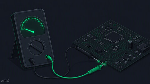
| Insulation resistance (IR) | Megger test per IEC 62446-1 method (test voltage per system voltage class) | ≥1 MΩ for typical residential arrays; investigate anything near the floor |
| Continuity of EGC | Low-resistance ohmmeter from array frame to service ground | Near-zero ohms, no open segments |
The IR test is the one installers skip and the one I'd defend in court. A string that passes Voc with a chafed conductor against the rail will pass today and ground-fault in the first wet spring. Five minutes with a megohmmeter beats a callback, every single time. The PV wire guide explains which insulation failures this test catches.
AC-Side Verification
| Checkpoint | Method | NEC / Standard Basis |
|---|---|---|
| Breaker sizing on inverter output | Verify OCPD ≥ 125% of inverter continuous output current | NEC 690.8, 705.28, 240.6 |
| Conductor ampacity | Match conductor to OCPD with derating for conduit fill and temperature | NEC Table 310.16 |
| Point of interconnection | Load-side breaker within busbar limits, or supply-side tap per rules | NEC 705.12 |
| Voltage at inverter terminals | Meter L-L and L-N under no-load and loaded conditions | Utility nominal ±5%; check for high service voltage that will trip the inverter daily |
| Disconnect operation | Exercise every disconnect; verify lockable and labeled | NEC 690.13–690.15 |
Service voltage deserves emphasis. I chased a "defective" inverter that faulted every sunny afternoon; the service ran 252 volts and the inverter was doing exactly what UL 1741 told it to. One call to the utility for a tap change fixed what no replacement unit ever would have. Measure before you blame. The wire sizing guide and disconnect guide backstop the table.
The Energization Sequence
Order matters. This is the sequence I've standardized across crews:
- All disconnects open, modules covered. Verify zero-energy state.
- Close the battery/storage disconnect first on hybrid systems, if equipped — let the storage stabilize the DC bus.
- Energize the AC side. Close the inverter's AC breaker; the unit boots, self-tests, and waits for DC.
- Uncover one string, close its DC disconnect. Watch the inverter recognize the input, log the voltage.
- Bring remaining strings online one at a time. Any anomaly isolates to the string you just energized — this is why you don't energize everything at once.
- Witness first production. Confirm power flow direction, reasonable wattage for conditions, no fault codes.
- Configure monitoring. Gateway online, per-string or per-module reporting verified, alerts set, customer account created.
- Grid-interactive settings. Verify the correct grid profile for your utility and AHJ — the wrong profile is an instant red tag in jurisdictions that check.
Functional and Performance Verification
Energized isn't commissioned. The functional tests prove the system does what the contract says:
| Verification | How | Pass Standard |
|---|---|---|
| Production sanity check | Compare instantaneous output to array size and irradiance | Example: 8 kW array at solar noon, clear sky, mild temp → 6.4–7.4 kW (80–92% of nameplate) is healthy |
| String balance | Per-string current or power comparison | Identical strings within ~5–10% of each other in identical conditions |
| Rapid shutdown function | Initiate RSD, verify module-level shutdown per 690.12 | Controlled conductors drop below limits within required time |
| Backup/islanding test (storage systems) | Open the main breaker deliberately | Transfer happens within spec, backed-up loads stay live, system re-synchronizes on restore |
| Monitoring data integrity | Compare app-reported production to meter readings | Values agree within a few percent |
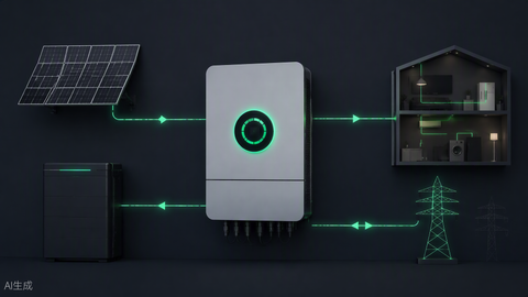
The islanding test gets skipped because it feels theatrical. Do it anyway, with the customer watching. It's the only test the customer will ever personally care about, and it surfaces misconfigured transfer settings while you still have tools in the truck. On the equipment side, this is where quality hybrid inverters and properly sized battery banks earn their price — a bank too small for the surge load fails this test in front of the homeowner.
Documentation: The Part That Outlives You
My commissioning packet, every job, no exceptions:
- As-built single-line diagram — the actual wire routing, not the permit set's intention
- String Voc/IR/polarity test records with date, irradiance, and temperature noted
- Torque documentation on terminations (value and tool, not a checkbox)
- Photos of every roof penetration, the label set, and open-junction-box wiring before close-up
- Inverter configuration export — grid profile, battery settings, firmware version
- Customer walkthrough sign-off covering shutoffs, monitoring app, and warranty contacts
That packet has settled two warranty disputes and one insurance claim in my career, all in my favor, all because contemporaneous records beat memory. It also makes the next service tech's job possible — and someday the next tech is you, squinting at your own work from nine years ago. Build the packet like it's evidence, because on the bad days, it is.
The Commissioning Mindset
Everything above reduces to a posture: assume the system contains exactly one mistake, and your job today is to find it. The crew that installs well and commissions lazily owns every latent defect they energized. The crew that tests in sequence, compares strings, and documents obsessively hands over systems that run boring for decades — and boring, in this trade, is the finest compliment a system can earn. Commission like you'll be the one answering the phone in year nine. You usually are.
The Defects Gallery: What Commissioning Actually Finds
Abstract checklists persuade less than the specific failures they catch. From my own commissioning logs, the recurring finds, in rough order of frequency:
| Defect | How Commissioning Catches It | What It Becomes If Missed |
|---|---|---|
| Reversed string polarity | Polarity check before energization | Destroyed inverter DC stage; fire risk |
| Under-torqued terminations | Torque verification with witness marks | Resistive heating, arcing, eventual failure |
| Chafed PV wire against rail edge | Insulation resistance test + visual walk-down | Ground faults in the first wet season |
| Mismatched strings on shared MPPT | String-to-string Voc comparison | Chronic underproduction, never diagnosed |
| Wrong grid profile selected | Configuration export review | Nuisance tripping; red tag in strict AHJs |
| Failed module bypass diode | String Voc ~5%+ below siblings | Hot spots, accelerated module degradation |
| Missing or wrong labels | Label checklist against 690.31/690.55 | Failed final inspection; first-responder hazard |
| High service voltage | Terminal voltage measurement under load | Daily overvoltage trips blamed on the inverter |
Every row on that table has cost someone a truck roll that a meter would have prevented. The pattern worth internalizing: none of these defects are exotic, and all of them are cheap to fix on commissioning day and expensive every day after.
Temperature Corrections: Getting Voc Math Right
The string voltage table in the DC tests only means something if you correct for temperature, because module voltage rises as cells cool. The procedure, per NEC 690.7 logic: take the module Voc at STC, multiply by the series count, then apply the correction factor for the site's record-low temperature from Table 690.7(A). Worked example with a common 450 W class module at 49.4 V Voc, twelve in series, at a site with a −10°C design low (factor 1.12):
| Step | Calculation | Result |
|---|---|---|
| String Voc at STC | 12 × 49.4 V | 592.8 V |
| Cold correction (−10°C) | 592.8 × 1.12 | 663.9 V |
| Against a 600 V inverter limit | 663.9 > 600 | FAILS — drop to 11 per string |
| Recheck at 11 modules | 11 × 49.4 × 1.12 | 608.6 V — still over; use 10 |
| Final at 10 modules | 10 × 49.4 × 1.12 | 553.3 V — passes with margin |
That iterative check is exactly what the design software does, but the commissioning tech who can run it longhand catches the field substitutions — the different module that showed up on the truck, the string that got rebalanced on the roof — that the paper design never saw. At commissioning, your measured Voc should land within a few percent of the temperature-corrected expectation for the conditions at test time. A string reading way low in cool, bright conditions is telling you about a miswire or a dead module before the inverter ever logs it.
Commercial Commissioning: Same Discipline, More Paper
Commercial and commercial-scale systems add layers rather than changing fundamentals. IV-curve tracing moves from recommended to expected — a proper curve tracer on every source circuit catches subtle mismatch and soiling patterns that Voc alone misses. Witnessed testing becomes contractual: the owner's rep or the utility's witness signs each test record in real time. Utility interconnection witness tests add anti-islanding verification and protection-settings documentation, and larger systems bring SCADA integration checks and revenue-grade meter verification. Budget accordingly: where residential commissioning runs two to four hours, a 500 kW commercial array can run two to four days across electrical tests, utility witness points, and punch-list cycles. The sequence, though — mechanical, DC, AC, energize in stages, verify function, document everything — scales without modification.
Tools of the Trade: The Commissioning Kit
The kit I trust, after years of refinement:
- True-RMS CAT III/CAT IV multimeter rated for the DC voltages you're measuring — check the rating, not the marketing.
- Clamp meter with DC current capability for string current verification without breaking connections.
- Megohmmeter / insulation tester with the test voltages IEC 62446-1 calls for at your system voltage class.
- Calibrated torque wrench covering the 5–20 Nm range that lugs and clamps actually spec, plus the paint pen for witness marks.
- Irradiance meter — production sanity checks are meaningless without knowing what the sun delivered during the test.
- IV curve tracer for commercial work and for forensic diagnosis on underperforming residential strings.
- Label printer and camera. The documentation is a deliverable, not an afterthought.
Skimp on the kit and every test becomes an estimate. The test equipment category exists because commissioning discipline starts at the tool crib.
The Handoff Conversation: Teaching the Customer Their System
Commissioning ends with a person, not a meter. The customer walkthrough is part of the deliverable, and the good ones cover the same ground every time: where every disconnect lives and which one to pull first in an emergency; what the monitoring app shows and what a normal day looks like in it; what the warranty covers and who to call; and the two or three behaviors that actually extend system life — keeping vents clear, reporting fault codes instead of resetting them silently, and calling before adding loads the system wasn't designed around. Twenty minutes here prevents the 9 PM phone calls. I've learned to make the customer physically operate the main disconnect once, with me watching — the person who has touched it will use it; the person who only heard about it will freeze. That walkthrough is also where reputation lives: the system may run for decades, but what the customer remembers is whether they understood what they bought when the truck pulled away.
Seasonal Timing and Commissioning Conditions
When you commission shapes what you can verify. A winter commissioning under flat grey skies won't show full production — set expectations and document the irradiance at test time so the "low output" complaint in May has context. A midsummer noon commissioning shows production beautifully but hides the cold-weather voltage behavior your 690.7 math was designed around. The honest answer to both: record conditions with every test, run the temperature-corrected expectations rather than nameplate comparisons, and where season limits verification, note the limitation in the commissioning report and schedule the follow-up check. A commissioning report that says "verified under 410 W/m² overcast, full production verification deferred to clear-day conditions" is worth more than a signature claiming a test nobody could have run that day.
When Commissioning Finds a Real Problem
Eventually the tests find something serious — a failed module, a manufacturing defect in an inverter, a design error that made it to the roof. The discipline that matters then: stop, document, and don't energize past the fault hoping it'll clear. Isolation procedure first — the affected string or unit comes offline and stays tagged. Documentation second — photos, test values, serial numbers, conditions. Manufacturer contact third, with the file complete, because warranty processes move at the speed of your paperwork. I keep a standing rule on my jobs: nobody "fixes" a commissioning anomaly by resetting it twice and hoping. Every fault has a reason, and the reason found on commissioning day costs a fraction of the reason found by smoke.
From Commissioning to Operations: Setting Up Year One
The commissioning report is also the baseline for everything that follows. A healthy system in month eleven should look like the commissioning data adjusted for season — and the only way to know is to keep the records where they'll be found. Set the owner's expectations for the first year: a production dip in smoke season or storm weeks is weather, not failure; a fault code that clears and returns is a message, not an annoyance; and the one-year service visit — terminal torque re-check, visual walk-down, monitoring data review — is cheap insurance on twenty-four remaining years. Systems that get that first-year attention settle into the decades of boring reliability every good install promises. The ones that don't eventually generate the phone call that starts with "it's been acting funny for a while." By then the fix is bigger, the records are colder, and the warranty conversation is harder. Commission well, document completely, and hand off like you mean it — the rest of the system's life is downhill from there. Keep the NEC code compliance guide bookmarked between jobs, and let the commissioning packet you built today be the baseline every future service visit measures against. The trades that last are built on exactly this kind of unglamorous rigor — test, record, verify, hand off — repeated on every roof until it stops feeling like procedure and starts feeling like craft. That's the real curriculum of a master electrician, and commissioning is where it's taught. Bring the meter, bring the torque wrench, bring the notebook — and don't leave until every row in the tables above has an answer. The system you commission carefully today is the system nobody calls about for the next twenty years — and that's the whole point of the trade's least glamorous, most valuable day. Do it right, every time, and let the record show. That's the job, done right, start to finish, no shortcuts, no skipped rows, no exceptions — the discipline is the deliverable, every single job, every single roof, in every season.
Frequently Asked Questions
What is solar commissioning?
Commissioning is the systematic verification that an installed solar system is safe, code-compliant, and performing to design before it's turned over to the owner — mechanical checks, electrical tests, sequenced energization, functional tests, and documentation.
How long does commissioning a residential system take?
Two to four hours for a straightforward residential rooftop with storage: an hour of mechanical walk-down, an hour of DC and AC electrical tests, then energization, functional verification, and the customer handoff.
What is an insulation resistance test and why does it matter?
A megohmmeter test per IEC 62446-1 that detects damaged conductor insulation and ground-fault paths before energization. A common acceptance floor is 1 MΩ for residential arrays. It catches defects that voltage tests alone miss.
Who can perform solar commissioning?
Requirements vary by jurisdiction — many require a licensed electrician for the electrical verification and interconnection sign-off. Regardless of licensing, the person commissioning needs the test equipment, the sequence, and the discipline to follow it.
What's the most common commissioning failure you find?
Skipped string comparison. Identical strings that disagree by more than a few percent are telling you something — a miswire, a shaded module, a failed diode — and the system will underperform for years if nobody reads the message on day one.
Does commissioning affect the warranty?
Yes. Manufacturers can require documented commissioning for warranty coverage, and installation-caused failures discovered later are far easier to resolve with dated test records. The commissioning packet is the system's birth certificate.