Why Correct Circuit Breaker Sizing Is Non-Negotiable


A circuit breaker is the only thing standing between a wiring fault and a structure fire. Size it too small and you chase nuisance trips forever. Size it too large and the breaker sits politely silent while the wire in the wall cooks. Neither failure mode is theoretical — we pull scorched breakers out of panels every month, and the story is almost always the same: somebody "fixed" a tripping breaker by swapping in a bigger one.

The National Electrical Code gives you a complete, mechanical procedure for getting this right. It lives in three places: Article 210 for branch circuits, Article 215 for feeders, and Article 240 for overcurrent protection itself. Master one rule — the 125% continuous-load rule — and eighty percent of residential and light-commercial sizing questions answer themselves.
This guide walks the whole procedure: the 125% rule, load calculation, wire ampacity matching under NEC 310.16, standard breaker ratings under NEC 240.6, temperature correction, voltage drop, and the special cases (motors, HVAC, EV chargers, solar backfeed) that trip up even experienced installers. Keep our standard breaker sizes chart open in another tab — it pairs with everything below.
The Critical NEC 125% Rule Explained

NEC 210.20(A), 215.3, and 230.42 all say the same thing: where a load is continuous — defined as running at maximum current for three hours or more — the overcurrent device must be rated at not less than 125% of that continuous load. Flip it around and you get the field version: a standard breaker should carry no more than 80% of its rating on a continuous basis. Same math, two directions:
- Sizing up: Continuous load × 1.25 = minimum breaker rating. A 16A continuous load needs at least a 20A breaker.
- Derating down: Breaker rating × 0.80 = maximum continuous load. A 50A breaker carries 40A continuous, max.
Why the margin? Thermal. A breaker's trip mechanism is a bimetal strip or an electronic analog of one, and it is calibrated to carry its rating in a 40°C open-air test — not bolted into a hot load center next to eleven other breakers that are also carrying load. The 125% headroom absorbs real-world enclosure heat, terminal resistance, and tolerance stack-up. Skip it and the breaker becomes the weak link that trips on the hottest afternoon of the year, which is precisely when your customer is watching.
Example: Warehouse LED Lighting
A lighting retrofit draws 32A of measured, honest continuous load — LED drivers run all business day, well past the three-hour threshold. Minimum conductor ampacity and breaker rating: 32A × 1.25 = 40A. So: 40A breaker, 8 AWG copper THHN (50A at 75°C, more than adequate), done. The rookie mistake is putting that 32A load on a 30A breaker because "32 is close to 30." It trips within the first week. The second rookie mistake is fixing that trip with a 50A breaker on the existing 10 AWG wire — now the wire is the fuse. Both errors trace back to not doing the one-line multiplication.
Breaker & Wire Size Calculator
NEC 240.6(A) standard sizes · 125% continuous-load rule (210.19/215.2) · 310.16 75°C ampacity
🧰 What you'd need
- Breaker in your calculated size → Circuit breakers
- Wire — THHN/THWN-2 in your gauge → Cerro wire & cable
- Disconnect / safety switch for the circuit → Eaton breakers & disconnects
Estimates for guidance only — NEC 240.4(D) small-conductor limits applied; ambient correction, conduit fill, and local amendments not included. Confirm final design with a licensed electrician and your AHJ.
Standard Breaker Sizes vs. Maximum Continuous Load
Memorize this table or print it and tape it inside the truck. It converts NEC 240.6(A) standard ratings into the continuous amps each can actually carry:
| Standard Breaker Rating (A) | Max Continuous Load (A) | Common Application |
|---|---|---|
| 15A | 12A | Residential lighting, general-use outlets |
| 20A | 16A | Kitchens, bathrooms, garages, dedicated appliances |
| 30A | 24A | Electric water heaters, clothes dryers |
| 40A | 32A | Electric ranges, small subpanels |
| 50A | 40A | Large electric ranges, Level 2 EV chargers |
| 60A | 48A | Large HVAC units, some EV chargers |
| 100A | 80A | Subpanels, commercial lighting banks |
| 200A | 160A | Main residential/small commercial service |
Calculating Your Total Electrical Load
Breaker sizing starts from the load, and the load comes from NEC Article 220 — or from nameplates and measurements when you're adding a circuit to an existing panel. Our complete guide to electrical load calculation runs the full Article 220 procedure; the condensed field flow is:
Step-by-Step Load Calculation Flowchart
- List every load on the circuit or service: nameplate VA or watts, volts, and whether it runs 3+ hours (continuous) or not.
- Convert everything to amps: I = VA ÷ V for single-phase; I = VA ÷ (V × 1.732) for three-phase.
- Separate continuous from non-continuous. Be honest — commercial lighting, EV charging, and any heating load that cycles to a thermostat for hours are continuous.
- Apply the multiplier: (continuous amps × 1.25) + (non-continuous amps × 1.00) = required breaker/feed rating.
- Round UP to the next standard size from NEC 240.6(A): 15, 20, 25, 30, 35, 40, 45, 50, 60, 70, 80, 90, 100, 110, 125, 150, 175, 200A and beyond.
- Check the wire: conductor ampacity from NEC Table 310.16 (75°C column for most terminations) must meet or exceed the load, and the breaker must protect the wire — with the 240.4(B) next-size-up allowance only when its conditions are met.
Real-World Calculation Example
A shop subpanel feeds: 24A of LED lighting (continuous), a 12A dust collector (non-continuous motor), and 8A of receptacles (non-continuous). Required rating: (24 × 1.25) + 12 + 8 = 50A. A 50A, 2-pole 240V breaker and 6 AWG copper feeder handles it cleanly. Notice the receptacles and motor don't get the 1.25 multiplier — only the lighting does. Mixing that up in either direction either wastes copper or creates a code violation, and I have personally red-tagged both versions at rough-in inspection.
Matching Breaker Size to Wire Ampacity

What Determines Wire Ampacity (NEC Table 310.16)
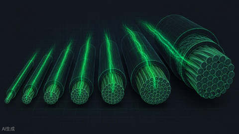
Ampacity is not one number — it's a column choice. NEC Table 310.16 rates copper conductors at 60°C, 75°C, and 90°C insulation classes. The trap: equipment terminals, not the wire's insulation, usually set the ceiling. Per 110.14(C), circuits 100A and under use the 60°C column unless the terminals are listed for 75°C — and virtually all modern breakers and panels are 75°C-listed, so the 75°C column governs daily practice. The 90°C column exists almost exclusively as a starting point for derating calculations, never as a final ampacity for breaker pairing.
Wire Gauge Ampacity and Recommended Breaker Size
| Copper Wire Gauge (AWG) | Ampacity at 75°C (THHN/THWN) | Max Standard Breaker Size | Note |
|---|---|---|---|
| 14 AWG | 15A* | 15A | Standard residential branch circuit; *240.4(D) limits it to 15A protection despite 20A table ampacity |
| 12 AWG | 20A* | 20A | Kitchen, bath, garage circuits; *240.4(D) caps at 20A despite 25A table value |
| 10 AWG | 35A | 30A | Water heaters, dryers — 240.4(D) caps at 30A |
| 8 AWG | 50A | 50A | EV chargers, electric ranges |
| 6 AWG | 65A | 60A | Round down — no standard 65A breaker exists |
| 4 AWG | 85A | 80A | Round down to protect wire safely (or 90A only if every 240.4(B) condition is met) |
| 2 AWG | 115A | 100A | Subpanels, large commercial feeds |
| 1/0 AWG | 150A | 150A | 150A services and feeders |
| 2/0 AWG | 175A | 175A | Common for 150–175A residential services |
| 4/0 AWG | 230A | 200A | Standard 200A service entrance (residential 310.12 allowance) |
We've pulled thousands of feet of 4/0 through EMT for 200A services, and the 4/0-with-200A-breaker pairing is the one every apprentice questions the first time: 230A ampacity, 200A breaker, protected with margin to spare. For the full wire-side treatment, see our NEC wire ampacity chart and the solar-and-generator wire sizing guide. The wire size calculator automates the lookup.
NEC 240.6 — Standard Circuit Breaker Sizes (A)
When your calculated rating falls between sizes, you round up to the next standard rating for the breaker, then make sure the conductor is still protected. The standard ampere ratings, straight from 240.6(A):
| Standard Breaker Ratings (A) | Typical Wire Pairing (Cu, 75°C) | Common Use Case |
|---|---|---|
| 15 | 14 AWG | General lighting, receptacles |
| 20 | 12 AWG | Kitchen, bath, garage, small appliance |
| 25 | 10 AWG | Heavy-duty appliances, some motors |
| 30 | 10 AWG | Water heaters, dryers, EV chargers |
| 35 | 8 AWG | Large appliances, sub-feeds |
| 40 | 8 AWG | Electric ranges, large EV chargers |
| 45 | 8 AWG | Commercial equipment |
| 50 | 6 AWG | EV Level 2, large ranges, welders |
| 60 | 6 AWG | HVAC, large subpanels |
| 70–100 | 2–3 AWG | Subpanels, commercial feeders |
| 110–200 | 1/0–3/0 AWG | Main service, large commercial |
| 225–600 | 4/0–500 kcmil | Industrial mains, switchgear |
Ambient Temperature Correction Factors (NEC 310.16)
Ampacities in Table 310.16 assume a 30°C (86°F) ambient. Attics in August and rooftop gutters in Phoenix laugh at that assumption. Apply 310.15(B) correction factors whenever conductors run hot:
| Ambient Temp (°C) | Ambient Temp (°F) | Correction Factor (75°C Wire) | Effective Ampacity of 10 AWG |
|---|---|---|---|
| 21–25 | 70–77 | 1.00 | 35A |
| 26–30 | 78–86 | 1.00 | 35A |
| 31–35 | 87–95 | 0.94 | 32.9A |
| 36–40 | 96–104 | 0.88 | 30.8A |
| 41–45 | 105–113 | 0.82 | 28.7A |
| 46–50 | 114–122 | 0.75 | 26.3A |
| 51–55 | 123–131 | 0.67 | 23.5A |
| 56–60 | 132–140 | 0.58 | 20.3A |
Translation: that 10 AWG run across a 55°C attic is a 23.5A conductor — under the 30A breaker it's still protected, but it can no longer serve a 30A continuous-load calculation. This is how rooftop solar circuits and desert HVAC disconnects get into trouble. Our NEC 690 disconnect and overcurrent guide covers the rooftop version of this problem.
Voltage Drop by Circuit Length & Breaker Size (120V/240V, Cu)
NEC 210.19(A) Informational Note recommends keeping branch-circuit voltage drop under 3% (5% total feeder + branch). It's technically advisory, but inspectors in most jurisdictions treat it as gospel, and so do we — long runs to barns, RV pedestals, and well houses fail on voltage drop long before they fail on ampacity:
| Circuit Length (ft) | Breaker / Load | Wire Size | Voltage Drop (120V) | Voltage Drop (240V) | Status |
|---|---|---|---|---|---|
| 50 | 20A | 12 AWG | 1.6% | 0.8% | OK |
| 100 | 20A | 12 AWG | 3.2% | 1.6% | OK at 240V, marginal at 120V |
| 100 | 30A | 10 AWG | 3.0% | 1.5% | OK |
| 150 | 30A | 10 AWG | 4.5% | 2.3% | OK at 240V only |
| 150 | 50A | 6 AWG | 2.4% | 1.2% | OK |
| 200 | 50A | 6 AWG | 3.2% | 1.6% | OK at 240V only |
| 200 | 50A | 8 AWG | 5.1% | 2.6% | Over 3% at 120V — upsize wire |
| 250 | 60A | 4 AWG | 2.5% | 1.3% | OK |
The 240V column is the cheat code for long runs: doubling the voltage halves the percentage drop for the same watts, which is exactly why we spec 240V circuits for outbuildings even when the load could run on 120V.
Critical compliance point: always use the 75°C column for final breaker-to-wire pairing on modern equipment. The 90°C column is for derating math only. Writing a 90°C ampacity on a permit drawing is the fastest way we know to earn a correction notice.
Sizing Breakers for Specialized Loads
Motors (NEC Article 430)
Motors break the 125% rule's logic because their inrush current — six to eight times running amps for a split second — would trip any breaker sized at 125% of full-load current. Article 430 solves this by separating the jobs: overload protection (heaters or an electronic relay, sized near 115–125% of motor FLA) protects the motor; the branch breaker protects against shorts and ground faults and may be sized up to 250% of motor FLA per Table 430.52 for an inverse-time breaker. A 10A-FLA compressor on a 25A breaker looks wrong to a residential electrician and is perfectly correct under Article 430.
HVAC Systems (HACR-Rated Breakers)
For air-conditioning equipment, the nameplate does the work. Look for "Minimum Circuit Ampacity" (MCA) and "Maximum Overcurrent Protection" (MOP or Max Fuse/Breaker). The manufacturer has already applied the motor rules — your job is simply: conductor sized to MCA, breaker no larger than MOP. A condenser marked MCA 28A / MOP 45A wants 10 AWG copper and up to a 45A breaker. Pairing it with a 30A breaker because "the wire is 10 gauge" causes exactly the nuisance trips the MOP number exists to prevent.
EV Chargers (Level 2 — Continuous Load)
EV charging is the poster child for continuous loads: four to ten hours at full current, every night. A 48A charger requires 48 × 1.25 = 60A → a 60A breaker and 6 AWG copper. This is code law under NEC 625.42, not a suggestion. It's also why "I plugged my 40A charger into the dryer outlet" ends with a melted receptacle — the dryer circuit is a 30A non-continuous design. If the charger project also involves new runs, our 240V outlet wiring guide covers receptacle-side details, and we stock the hardware — from Enphase HCS-40 EVSE to the Generac 48A Level 2 charger — in the EV charger collection.
Solar Backfeed Breakers — The NEC 120% Rule
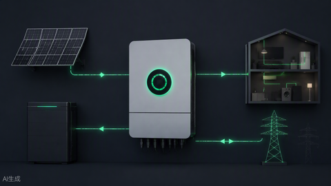
When solar backfeeds a panel through a breaker, NEC 705.12(B) limits the sum of the main breaker plus the PV breaker to 120% of the busbar rating. On a standard 200A panel with a 200A main: (200 × 1.20) − 200 = 40A maximum solar breaker. That caps a backfed residential system at 7.7 kW AC (40A × 240V × 0.8 continuous ÷ ... in practice a 9.6 kW-DC array on a 7.6 kW inverter). Bigger systems need a line-side tap, a main breaker downgrade, or a panel with a 225A bus and 200A main — which opens the PV allowance to 70A. Size the backfeed breaker like any continuous load: inverter max output current × 1.25, round up to standard.
Circuit Breaker Market Context

One commercial reality worth knowing: breaker compatibility is brand-locked. Square D QO breakers fit QO panels; Homeline fits Homeline; Eaton BR fits BR. "Classified" breakers exist as cross-brand replacements, but many inspectors and all panel warranties prefer the listed match. When we help customers plan a panel upgrade or a solar interconnection, the breaker line often chooses the panel line. Source genuine breakers and panels together — the gray market for counterfeit breakers is real, and a counterfeit 20A breaker is a 20A-shaped fire hazard. Our electrical components and electrical supplies collections carry the genuine article, and the electrical hub organizes the guides.
Breaker Types: Standard, GFCI, AFCI, and Dual-Function
Amp rating is only half the selection. The protection type matters just as much, and the NEC now mandates specific technologies by room and circuit:
| Breaker Type | Protects Against | Where the NEC Requires It (2023 cycle) | Field Note |
|---|---|---|---|
| Standard thermal-magnetic | Overload and short circuit | Baseline everywhere | The default for dedicated appliance circuits |
| GFCI breaker | Ground faults (shock protection) | Bathrooms, kitchens, garages, outdoors, basements, laundry, within 6 ft of sinks (210.8) | Costs more than a GFCI receptacle but protects the entire run |
| AFCI breaker | Arc faults (fire protection from damaged/arcing conductors) | Bedrooms, living areas, most 120V 15/20A circuits in dwellings (210.12) | Combo AFCI + shared neutrals = headaches; use a dual-function on multi-wire branch circuits |
| Dual-function (AFCI+GFCI) | Both | Kitchen and laundry circuits needing both protections | One device, one space, fewer nuisance callbacks |
Budget reality: a standard 20A single-pole costs a few dollars; a dual-function costs eight to ten times that. On a 42-space new-build panel, the AFCI/GFCI mandates add several hundred dollars of breakers — line-item it in the bid instead of eating it at trim-out.
Panel Spaces and Service Capacity: The Constraint Nobody Checks First

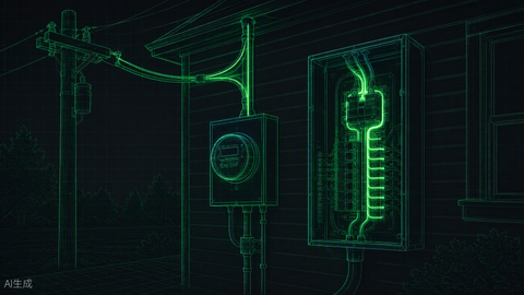
Before adding any breaker, two checks. First, physical spaces: tandem ("cheater") breakers only work where the panel's labeling allows them, and many 20-space panels max at 20 circuits with zero tandem positions. Second, service capacity: the panel's main breaker rating must cover the new load under an Article 220 calculation — adding a 60A EV circuit to a loaded 100A service isn't a breaker problem, it's a service-upgrade problem. Our bus bar guide explains what the panel's metal can actually carry.
Worked Example: Full Residential Service Sizing
Tie it all together with a 2,400 sq ft all-electric home: general load, range, dryer, water heater, dishwasher, disposal, 5-ton heat pump, and a 40A EV charger.
| Load Item | Raw Value | NEC Treatment | Calculated VA |
|---|---|---|---|
| General lighting + receptacles | 2,400 sq ft × 3 VA | 220.41 — 3 VA per sq ft | 7,200 |
| Small-appliance + laundry circuits | 3 circuits × 1,500 VA | 220.52 | 4,500 |
| Subtotal → demand factor | 11,700 VA | 220.42: 3,000 @100% + 8,700 @35% | 6,045 |
| Range (12 kW) | 12,000 VA | Table 220.55 → 8 kW | 8,000 |
| Dryer | 5,000 VA | 100% nameplate (min 5,000 per 220.54) | 5,000 |
| Water heater + dishwasher + disposal | 6,900 VA | 220.53: 4+ fixed appliances @75% (range excluded) | 5,175 |
| Heat pump (larger of heat/cool) | 6,000 VA | 220.60 — non-coincident loads | 6,000 |
| EV charger (9,600 VA) | 9,600 VA | 220.57 — 100%, no diversity | 9,600 |
| Total service load | — | — | 39,820 VA |
39,820 VA ÷ 240V = 166A. Round up to the next standard service: 200A. Note what demand factors did: raw nameplates summed to over 51 kVA — a 225A+ design — while the code-legal calculation landed at 166A. That discipline is the difference between a routine 200A service and an unnecessary 320A one. And every breaker inside that panel still gets sized individually by the 125% rule — the service calculation and the branch-circuit calculation are separate exercises that happen to share a worksheet.
Common Sizing Mistakes and How to Avoid Them

Mistake 1: Using 90°C Ampacity for Breaker Sizing
THHN is 90°C-rated insulation, so 12 AWG "carries 30A" — except the breaker terminals are 75°C-rated, which caps the same wire at 25A table ampacity and 20A of allowed protection under 240.4(D). Use 90°C numbers only as the pre-derating starting value; land the final design on the 75°C column.
Mistake 2: Oversizing the Breaker to Stop Tripping
A tripping breaker is a message, not a malfunction. If a 20A breaker trips, the circuit is telling you the load exceeds the design — or a fault exists. Swapping in a 30A breaker on 12 AWG wire silences the message by disabling the protection. I've opened walls where this exact swap cooked the NM cable jacket brittle; the house survived only because the run was short. Fix the load split, find the fault, or pull a new circuit — never "fix" tripping with a bigger breaker.
Mistake 3: Ignoring Voltage Drop on Long Runs
Ampacity protects against heat; voltage drop protects against performance. A 150-foot 120V run on 12 AWG is legal by ampacity and useless in practice — motors run hot, EVSE units fault out, and LED drivers flicker. Check the table above; upsizing one or two gauges is cheap insurance next to trenching labor.
Mistake 4: Forgetting to Apply NEC Demand Factors
On the service side, Article 220 demand factors cut realistic service sizes by 30–40% versus raw nameplate sums. Skipping them means buying a 320A service where 200A was code-adequate — thousands of dollars of copper, panel, and utility coordination that no one needed. Our load calculation guide walks the demand-factor tables line by line.
Three-Phase and Commercial Considerations
Everything above assumed 120/240V single-phase. Commercial work runs 120/208V and 277/480V three-phase, and the math changes in exactly one place: the current formula gains a √3. I = VA ÷ (V × 1.732). A 30 kVA 208V three-phase load pulls 30,000 ÷ (208 × 1.732) = 83A → sized continuous, 83 × 1.25 = 104A → a 110A or 125A breaker depending on the load profile. Two traps specific to three-phase work: first, 277V lighting circuits need breakers rated for the voltage — a slash-rated 120/240V breaker has no business on a 277V circuit; second, balanced three-phase panels still need per-phase load tracking, because "the panel has capacity" means nothing if phase B is already carrying 90% of it.
Diagnosing Nuisance Trips Without Touching the Breaker Size

When a breaker trips and the math says it shouldn't, work this table before anyone reaches for a bigger frame:
| Symptom | Most Likely Cause | Correct Fix |
|---|---|---|
| Trips after 30–90 minutes under steady load | Thermal overload — load near rating, hot panel, or failing breaker | Clamp the actual current; if within 80%, inspect terminal torque and replace a heat-damaged breaker |
| Instant trip on reset | Dead short or ground fault downstream | Disconnect loads, megger the run, find the fault — never upsize |
| Trips only when a motor starts | Inrush exceeding magnetic trip on a misapplied breaker | Verify Article 430 sizing; check for a failing capacitor or seized bearing raising LRA |
| AFCI/GFCI trips with no fault found | Shared neutral, leaky appliance, or incompatible LED driver | Isolate circuits one at a time; shared neutrals need 2-pole or dual-function handling |
| Trips only on hot afternoons | Ambient heat derating + marginal continuous load | Reduce load, improve panel ventilation, or redistribute circuits across phases |
Terminal torque deserves its own sentence: a breaker landing torqued to the value printed on its label — typically 20–45 in-lbs depending on frame and wire size — runs measurably cooler than a hand-snug one. Loose terminals are the leading cause of heat-damaged breakers we see in the field, and a calibrated torque screwdriver costs less than one callback.
Breakers vs. Fused Disconnects: When Each Wins
Breakers aren't the only overcurrent device, and in two situations they're not even the best one. Fused disconnects still own high-fault-current territory: where available fault current exceeds a standard breaker's 10kA interrupting rating — common near large services and transformers — current-limiting fuses with 100kA+ ratings handle what a residential frame cannot. Second, equipment that must be visibly, positively isolated for service (rooftop HVAC, solar inverters per NEC 690.15) often specifies a fused or non-fused pullout disconnect within sight of the unit; the breaker in the panel stays, but the disconnect becomes the service point. For everything else, the breaker's resettability wins — nobody wants to hunt fuses at 2 a.m. in a rainstorm, and that is exactly when the fault will happen.
Maintenance: The 60-Second Breaker Health Check
Once a year on commercial panels, and any time a cover comes off residentially: feel each breaker face for abnormal warmth after an hour of load, look for discoloration around the terminal lug, and exercise each breaker (off, then on) to keep the mechanism free. NFPA 70B formalizes this for commercial facilities; homeowners get ninety percent of the benefit with an infrared thermometer and ten minutes.
How PES Supply Supports Your Project
We stock the full chain: genuine breakers, THHN/THWN copper by the spool (8 AWG through service-entrance sizes), load centers, disconnects like the DU221RB safety disconnect, and PV-rated overcurrent devices such as the MidNite MNEPV50 for solar DC circuits. Bring us the load list and the one-line; we'll kit the materials to match, with the NEC compliance guide as the shared checklist between your crew and our counter.
Frequently Asked Questions About Circuit Breaker Sizing
What is the NEC 125% rule for circuit breakers?
For any continuous load (3+ hours at max current), the breaker must be rated at least 125% of that load. Equivalently, a standard breaker may carry only 80% of its rating continuously: a 20A breaker maxes at 16A continuous.
What is the 80% rule, and is it the same thing?
Yes — it's the reciprocal framing of the 125% rule. Breaker × 0.8 = maximum continuous load; load × 1.25 = minimum breaker. Both come from NEC 210.20(A) and 215.3.
What size breaker do I need for a 240V water heater?
A typical 4,500W water heater draws 18.75A at 240V (4,500 ÷ 240). As a continuous load: 18.75 × 1.25 = 23.4A, so a 25A or the conventional 30A breaker with 10 AWG copper. Most manufacturers' instructions specify a 30A circuit.
Can I use a breaker rated lower than the wire?
Yes — undersizing the breaker relative to wire ampacity is always safe and often deliberate (a 20A breaker on 10 AWG for a long run to control voltage drop). The reverse — breaker larger than the wire's ampacity — is the prohibited direction, outside narrow motor and 240.4(B) exceptions.
Can I upsize a breaker to stop nuisance tripping?
Never on the same wire. The breaker exists to protect the conductor; oversizing it removes the protection and turns the wire into the fuse. Diagnose the overload or fault instead.
How do I size a breaker for a motor?
Per NEC Article 430: overload protection near 115–125% of motor full-load amps, and an inverse-time branch breaker up to 250% of FLA per Table 430.52 to ride through starting inrush.
What is the solar backfeed breaker size limit?
Under NEC 705.12(B), main breaker + PV breaker ≤ 120% of busbar rating. A 200A panel with a 200A main allows a 40A PV breaker maximum; larger solar systems need a line-side tap, main downgrade, or a 225A-bus panel.