Last Updated: April 2026 • Based on NEC 2026, ASCE 7 Wind Standards, and UL 2703 Certification Requirements
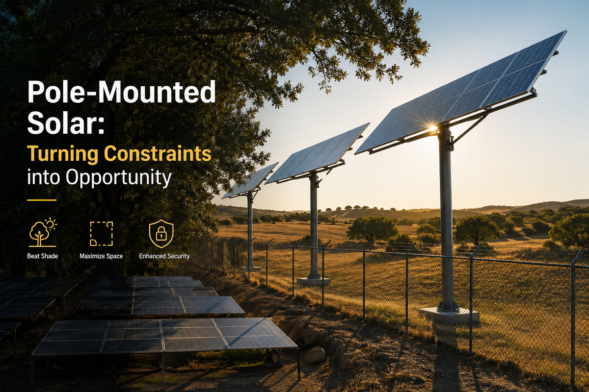
For solar installers, EPCs, and developers, rooftop and ground-mount systems are the default. But when a project site is constrained by shade, limited space, or security concerns, those standard solutions can kill the deal. This is the precise scenario where specifying solar panels on poles becomes a critical, value-driven alternative that can turn a non-starter project into a high-performing asset.
This guide provides the actionable framework for deciding when to deploy a pole-mounted solar array and how to execute it correctly. We cover the specific engineering, hardware selection, and compliance requirements to ensure your project is durable, code-compliant, and delivers maximum ROI for off-grid, agricultural, and security-focused applications.
⚡ Quick Answer
Pole-mounted solar arrays are the optimal choice for sites with shade obstructions, minimal land footprint requirements, security concerns, or off-grid/remote applications. They require site-specific structural engineering (ASCE 7 wind loads, frost depth, soil bearing), UL 2703-listed hardware, proper DC conduit runs, grounding, and voltage drop calculations - typically maintaining drop below 3% from panels to controller. Production gains of 25–35% are achievable with solar trackers.
Key Takeaways
Best Use Cases:- Off-grid sites, shaded properties, agricultural land, remote telecom/security, high-security commercial lots. >
- Pole and foundation specifications must be based on stamped load calculations - wind load (ASCE 7), ice/snow load, and panel "sail" area are non-negotiable inputs. >
- All mounting hardware must be UL 2703 listed. Torque every bolt to manufacturer spec with a calibrated torque wrench. >
- Keep DC voltage drop below 3% from panels to controller - this often requires upsizing wire gauge on runs over 50–100 feet. >
- The entire metallic structure - pole, racking, panel frames - must be bonded and connected to a dedicated grounding electrode. >
- Single-axis trackers add 20–25% annual production; dual-axis trackers add 25–35% - often the deciding factor in project financial viability. >
- Almost all jurisdictions require stamped engineering drawings and building permits for pole-mounted systems as permanent structures. >
- NABCEP-certified design support, Tier 1 panels, inverters, and mounting hardware with nationwide delivery and bundled kit pricing.
In This Guide
Why Pole Mounting Is a Game-Changer on Tough Sites
The mounting system you choose can make or break project ROI and performance. While rooftops and ground mounts dominate project discussions, knowing when to specify solar panels on poles gives you a critical edge in project bidding and execution. The primary driver is conquering site limitations that make standard solutions financially unviable. A project site with significant morning or afternoon shade from trees can render a ground-mount system a non-starter - elevating the array on a pole bypasses these obstructions entirely, transforming the project economics.
Smart Land Use and Better Security
On a farm or commercial property, every square foot of land has productive value. A sprawling ground-mount system takes that land permanently out of commission. Pole-mounted solar has a minimal footprint, enabling dual-use applications - powering an irrigation pump while active farming continues right up to the base of the pole. Security is another critical factor. In remote locations or commercial lots, ground-level panels are vulnerable to vandalism, theft, and accidental vehicle damage. Elevating an array 10–15 feet in the air is an immediate and cost-effective deterrent that requires no additional perimeter fencing.
Field Scenario: Remote telecom towers, environmental sensors, and security lighting almost exclusively use pole mounts. The solution delivers a small footprint, superior security, and optimal solar access in a single, robust package - a proven application for ensuring uptime in critical infrastructure where grid power is unavailable or cost-prohibitive.
Pole vs. Ground vs. Rooftop - Full Comparison
Deciding between mounting options comes down to a structured evaluation of site constraints, budget, and performance priorities. Use this table to quickly identify the best fit for your project's specific needs - from land use efficiency to total installed cost.
| Attribute | Pole Mount | Ground Mount | Rooftop |
|---|---|---|---|
| Land Use | Minimal footprint - ideal for dual-use land (agriculture, parking) | Significant footprint - requires dedicated, clear, level land | No additional land - uses existing roof space |
| Efficiency Potential | Highest - freely oriented and tilted; tracker-compatible | High - flexible orientation, but fixed angle | Moderate - constrained by existing roof angle and azimuth |
| Shade Avoidance | Excellent - elevates panels above ground-level obstructions | Poor - highly susceptible to nearby trees and structures | Good - can be affected by chimneys, vents, adjacent buildings |
| Security | Excellent - elevated position deters theft and vandalism | Vulnerable - requires fencing or additional security measures | Good - generally secure due to height |
| Installation Cost | High - significant foundation work (concrete, excavation) | Moderate - site prep and racking assembly required | Lowest - minimal site prep, attaches to existing structure |
| Ideal For | Off-grid sites, agricultural land, small arrays, high-security areas | Large-scale utility projects, properties with ample open land | Residential homes, commercial buildings with suitable roofs |
While pole mounts carry a higher upfront cost due to foundation work, their ability to maximize production in challenging locations often delivers a faster and more reliable return on investment over the system's 25-year life. This is especially true when the alternative is a rooftop system that underperforms due to shade, or a ground mount that occupies prime agricultural or commercial land.
A Proven, Time-Tested Method
Using poles for solar is not a new trend. Pole-mounted systems have a long track record in critical infrastructure - particularly for bringing power to rural areas since the late 20th century. Today they power everything from large utility projects to remote street lighting and agricultural irrigation. As reported in Utility Dive and other industry publications, finding smart deployment strategies for constrained sites is increasingly critical, and pole mounting remains one of the most practical tools in an installer's toolkit.
Specifying the Right Pole and Foundation
A pole-mounted solar array is a 25-year power-generating asset, and its entire operational lifespan hinges on the integrity of its structural base. Specifying the pole and foundation is a non-negotiable engineering task - not a procurement guess. It requires a calculated, site-specific process to ensure the structure withstands decades of wind, snow, ice, and environmental stress without failure.
Calculating Total System Load
To correctly specify a pole, every force it will encounter must be accounted for:
Panel and Hardware Weight (Static Load):- Sum the total weight of all panels, mounting racks, and hardware. A typical 400W panel weighs approximately
- a 4-panel array is 200 lbs before adding the steel racking structure itself.
- Consult local building codes and
- standards to determine the design wind speed for the project location. A coastal Florida site faces fundamentally different structural requirements than an inland Ohio installation.
- In cold climates, accumulated ice and snow can add hundreds of pounds of downward and eccentric force - a structural failure mode that cannot be ignored in northern project planning.
Guidance for Procurement and Developers: Never accept a generic, off-the-shelf pole specification. Require that your EPC or structural engineer provides stamped load calculations based on your specific site conditions and the exact equipment being installed. This documentation is your protection against catastrophic structural failure and is a mandatory component of your permitting package.
Choosing the Right Pole Material
With accurate load calculations complete, select the appropriate pole material. Each involves trade-offs in strength, longevity, cost, and installation complexity:
| Material | Pros | Cons | Best For |
|---|---|---|---|
| Galvanized Steel | Extremely high strength; resilient in high-wind zones; designed for 25+ year lifespan | Heavy - requires equipment for installation; higher upfront material cost | Commercial, utility, and high-wind zone applications where maximum durability is required |
| Aluminum | Lightweight; corrosion-resistant; easier to handle and install without heavy equipment | More expensive than steel for equivalent strength; susceptible to impact damage | Coastal high-salinity environments, or projects where minimizing installation labor is a priority |
| Treated Wood | Lowest upfront material cost; blends naturally into rural surroundings | Shorter lifespan; vulnerable to rot, insects, and environmental degradation over time | Rural, low-budget projects where aesthetics matter and a regular inspection schedule can be maintained |
Designing a Bulletproof Foundation
A pole is only as strong as its foundation. The choice between direct burial and a concrete pier foundation depends on a proper geotechnical site assessment. Your installer must verify the local frost line depth (to prevent frost heaving), confirm soil bearing capacity to handle static and dynamic loads, and call 811 to locate all buried utilities before any excavation begins. A properly engineered foundation ensures your solar panels on poles remain stable and fully productive for the system's entire operational life.
⚠️ Always Call 811 Before Excavating
Striking a buried gas line, electrical cable, or water main during foundation excavation is a project-ending emergency. Call 811 (Call Before You Dig) at least 3 business days before breaking ground. This service is free, legally required in most jurisdictions, and takes less than 5 minutes. No exceptions.
Selecting and Installing Mounting Hardware
The mounting hardware is the critical mechanical link between thousands of dollars in solar panels and the pole. Specifying cheap, non-certified hardware is a primary point of failure that can turn a valuable generating asset into scrap metal in a single storm. Hardware selection is an engineering decision - not a cost-cutting opportunity.
Three Primary Mount Types
Top-of-Pole Mounts:- Sit directly on top of the pole - ideal for smaller systems of
- . Provide excellent solar exposure and allow easy seasonal tilt adjustments without tools in many designs.
- Hardware bolts 1–2 panels to the side of the pole. The standard solution for small dedicated loads such as security cameras, gate openers, remote sensors, or single-panel battery charging stations.
- For larger arrays of
- , a dedicated engineered racking system is required. These robust structures are specifically designed to manage the significant combined weight and wind load of a larger solar array on a single pole.
Hardware Selection Workflow
① Define array size (number and wattage of panels)
↓
② Is it 1–2 panels for a dedicated small load?
↓ Yes → Side-of-Pole Mount ↓ No → Continue
↓
③ Is it 2–4 panels on a single pole?
↓ Yes → Top-of-Pole Mount ↓ No → Continue
↓
④ 4+ panels → Engineered Multi-Panel Racking System required
↓
⑤ Verify all hardware is UL 2703 listed
↓
⑥ Torque every bolt to manufacturer spec with calibrated torque wrench
↓
⑦ Apply anti-seize lubricant on all stainless steel fasteners
Pro Tip for Installers: Always use anti-seize lubricant on stainless steel bolts and nuts. Stainless hardware is highly prone to galling (cold welding), where threads seize permanently during tightening. A small amount of anti-seize compound prevents the need to grind or cut off a seized bolt - saving significant time and hardware cost on site.
Confirming all hardware carries UL 2703 listing is non-negotiable. This certification proves the hardware has passed rigorous testing for electrical bonding, grounding continuity, and mechanical strength in solar applications. For a comprehensive hardware overview, see our full guide to solar panel racking systems.
Mastering Electrical Wiring and Integration
Wiring a pole-mounted solar array presents unique challenges compared to a rooftop installation. Exposed conduit runs and longer wire distances demand precision to mitigate both efficiency losses and safety hazards. Incorrect execution leads to premature component failure, NEC violations, and costly rework on an elevated system.
Wire Protection and Grounding
Two Non-Negotiable Wiring Requirements
- All DC wiring descending the pole must be enclosed in
- Schedule 80 PVC or galvanized steel. Leaving USE-2 or PV wire exposed on a pole is a direct NEC violation subject to immediate inspection failure.
- The entire metallic structure - pole, racking, and all panel frames - must be bonded together and connected to a dedicated grounding electrode (typically a ground rod driven at the pole base). This provides the fault current dissipation path that prevents the structure from becoming energized.
Sizing Wires to Beat Voltage Drop
Voltage drop is the primary performance killer in pole-mounted systems. The extended DC wire run from an elevated array to ground-level equipment causes energy loss proportional to run length and wire gauge. In low-voltage off-grid systems (12V/24V), even modest voltage drop can impair battery charging and reduce overall system efficiency significantly. The industry standard is to maintain voltage drop below 3% from panels to the charge controller or inverter. This frequently requires upsizing conductor gauge beyond what a comparable short rooftop run would demand - a 100-foot run may require upgrading from 10 AWG to 6 AWG wire.
For a detailed walkthrough of DC wire sizing calculations, consult our guide on solar panel wiring basics.
Guidance for Commercial EPCs: For remote off-grid assets, microinverters mounted directly behind each panel convert DC to AC at the source - eliminating DC voltage drop on the homerun entirely. This simplifies wiring, eliminates long DC homerun sizing calculations, and enhances remote O&M monitoring down to the individual panel level, significantly reducing the cost of diagnosing performance issues at remote sites.
Connection Sequence and System Integration
A logical, code-compliant connection sequence is essential for safety, performance, and future serviceability:
① Panels → Weatherproof Junction Box (mounted on racking)
↓
② DC Surge Protection Device (SPD) - lightning strike protection
↓
③ DC Homerun inside conduit - down the pole to grade level
↓
④ Lockable DC Disconnect Switch - accessible at pole base
↓
⑤ String Inverter or Solar Charge Controller input terminals
Boosting Performance with Solar Trackers
A static fixed-tilt pole mount is optimized for only one period of the day - solar noon. A tracker transforms a pole-mounted system from a good asset into a high-performance powerhouse by keeping the panels aimed directly at the sun from dawn until dusk. For developers and asset owners evaluating project economics, the additional yield from a tracker is frequently the deciding factor that pushes a project from marginal to financially viable.
Single-Axis vs. Dual-Axis Trackers
Single-Axis Trackers:- Follow the sun on one axis - typically east to west. Simpler, less expensive, and lower maintenance than dual-axis. A cost-effective choice for maximizing daily production without the complexity of full two-axis tracking. Typical production gain:
- over a fixed system.
- Move on both east-west (azimuth) and north-south (elevation) axes - tracking the sun's daily arc AND its seasonal height changes. The premium solution for capturing maximum possible annual sunlight. Typical production gain:
- over a fixed system.
Field Scenario - Agricultural Water Pump: For a remote irrigation pump that must operate consistently throughout the day, a dual-axis tracker is a strategic investment. The additional power captured during the early morning and late afternoon "shoulder hours" meaningfully extends the pump's daily run time, delivering a clear operational return that justifies the higher capital cost over a 5–7 year payback window.
Tracker Production Gain vs. Fixed-Tilt Systems
Adding a tracker to a pole-mounted solar array increases annual energy production by 20–35% depending on tracker type and geographic latitude. In high-value remote installations - where every kWh of production directly offsets expensive diesel generation or extends battery autonomy - the tracker ROI case is compelling.
| System Type | Annual Production Gain vs. Fixed | Complexity | Best Application |
|---|---|---|---|
| Fixed Tilt | Baseline (0%) | None - no moving parts | Budget-constrained projects, low O&M sites |
| Seasonal Tilt Adjustment | +5–15% annually | Manual - twice-yearly adjustment | Top-of-pole mounts with accessible adjustment hardware |
| Single-Axis Tracker | +20–25% annually | Motorized - east-west axis only | Commercial off-grid, agricultural pumping, cost-effective tracking |
| Dual-Axis Tracker | +25–35% annually | Motorized - both azimuth and elevation | Maximum yield applications: telecom, critical infrastructure, high-value remote sites |
Your Long-Term Maintenance and Inspection Plan

A pole-mounted solar array is a 25-year power-generating asset. Treating it as a "set it and forget it" installation is a direct path to performance degradation, structural failure, and eventual loss of the asset. A proactive Operations and Maintenance (O&M) plan is essential to protect the investment and ensure sustained reliability - particularly for remote off-grid sites where a failure means total loss of power to critical loads.
Structural Integrity Checks
A visual structural inspection is mandatory after any severe weather event - high winds, heavy snow, or ice accumulation:
Structural Inspection Checklist
- Check for soil erosion around the base. Verify the pole remains perfectly plumb - any lean indicates a foundation issue requiring immediate geotechnical review.
- Annually spot-check torque on key mounting bolts per manufacturer specifications. Wind-induced vibration causes gradual loosening over time.
- Inspect all steel components - especially welds and bolt holes - for surface rust. Address immediately to prevent structural degradation; surface rust left untreated accelerates to structural failure.
- Verify all conduit seals and weatherproof fittings remain intact. Inspect for animal damage, UV degradation, or physical impact on exposed conduit sections.
Electrical and Performance Monitoring
The system's health is best diagnosed through its electrical performance data. Regular monitoring is the fastest way to detect issues before they cause significant downtime or damage. For taller or hard-to-access installations, integrating drone inspection with thermal imaging is increasingly the standard for safe, efficient O&M - identifying hotspots, failed cells, and connection issues without climbing.
Pro Tip for Asset Managers: Establish a clear performance baseline using the system's monitoring software during the first 2–4 weeks post-commissioning. A sudden weather-independent drop in output is a red flag requiring immediate investigation - it indicates a damaged wire, loose connection, or failed component. Catching this early prevents cascading damage and avoids extended downtime on remote systems.
This proactive O&M approach is critical at scale. Globally, 380 GW of new solar capacity was added in the first half of 2025 alone - and resilient pole-mounted systems in off-grid and remote applications are a growing part of this expansion, making structured maintenance programs increasingly critical for the industry as a whole.
Top Pole Mount Solar Questions Answered
How many panels can I put on a single pole?
This is an engineering question, not a rule of thumb. While a standard Schedule 40 steel pole can typically support 4–8 large panels, the true capacity is determined by a site-specific structural analysis accounting for: pole diameter, wall thickness, and material grade; total panel array surface area (the "sail" effect under wind load); local design wind speed and snow load; and the rated capacity of the racking system. Never specify a panel count without a structural engineer's sign-off on the combined load calculation.
Do I need a permit for a pole-mounted solar system?
Yes - in almost all jurisdictions. A pole-mounted system is a new permanent structure involving significant excavation and groundwork. Local building departments require stamped engineering drawings for permit review, verifying that foundation depth, pole specifications, and racking comply with local wind load, frost line, and NEC electrical safety codes. Skipping the permitting process risks a stop-work order and mandatory tear-down-and-rebuild - a far more expensive outcome than the permit itself.
Can I adjust the tilt angle seasonally?
Yes - and you should. This is a key operational advantage of top-of-pole mounts over fixed rooftop systems. Many are designed for easy manual seasonal tilt adjustments: steeper in winter to capture the low sun angle, shallower in summer. This simple twice-yearly adjustment can increase annual energy production by 5–15% compared to a fixed optimal-average tilt. For complete setup guidance, see our resource on general solar installation practices.
What are the NEC requirements specific to pole-mounted solar wiring?
Key NEC requirements for pole-mounted arrays include: all DC wiring must be enclosed in approved conduit (Schedule 80 PVC or galvanized steel) along the pole; a lockable DC disconnect must be installed at an accessible location at or near the pole base; the metallic structure must be fully bonded and grounded to a dedicated grounding electrode; a DC surge protection device (SPD) must be installed to protect against lightning surges; and all weatherproof enclosures must carry an appropriate NEMA wet location rating.
When is a tracker worth the extra cost?
A tracker becomes financially justified when the additional annual energy production (20–35%) creates enough additional value to offset the higher capital cost within an acceptable payback period - typically 3–7 years depending on local energy value and system size. The case is strongest for: remote off-grid systems where every kWh directly offsets expensive diesel generation, agricultural pumping where extended daily run time has direct operational value, and commercial sites where production-based incentives (REC credits, net metering) monetize every additional kWh generated.
Build Your Pole-Mounted Solar Project Right
Whether you're planning a single off-grid pole mount or a multi-unit commercial setup, the PES Supply team offers NABCEP-certified design support and a full catalog of Tier 1 solar panels, inverters, and mounting hardware - engineered to last 25 years in the field.
Request a Project Quote Shop Solar PanelsRelated Guides
- DC conductor sizing and voltage drop calculations for pole runs >
- Complete system setup practices for all mount types >
- Size DC disconnect and AC breakers for your pole-mounted system >
- Seasonal production benchmarks to model tracker ROI >
- NABCEP design support, Tier 1 panels, and pole mount hardware
About PES Supply
PES Supply is a nationwide distributor of Tier 1 solar panels, inverters, battery storage systems, EV charging hardware, racking and mounting systems, generators, and complete electrical project kits. With 12+ distribution hubs, 3,800+ in-stock SKUs, NABCEP-certified design support, and a network of 8,500+ solution providers, PES Supply serves contractors, EPCs, developers, and facility owners with fast delivery, expert procurement guidance, and warranty-aligned supply chain coordination.
Location: 1507 Portland Ave, Louisville, KY, United States | Phone: 1 888-876-0007 | Website: www.portlandiaelectric.supply
Article: Solar Panels on Poles: Engineering, Hardware, Wiring, and Installation Guide for EPCs and Installers
Category: Solar Energy | Pole Mounting | Off-Grid Systems | Agricultural Solar | EPC Resources
Last Updated: April 2026 • Based on NEC 2026, ASCE 7, and UL 2703 Certification Requirements
Disclaimer: Structural specifications, load calculations, and electrical designs referenced in this article are for informational purposes only. Always obtain stamped engineering drawings from a licensed structural engineer and verify compliance with local building codes and the Authority Having Jurisdiction (AHJ) before installation.
Related Resources:
- Best Solar Panels 2026 — Buyer's Guide
- EG4 vs Tesla Powerwall
- Qcells vs Trina vs JA
- Solar Inverter Buyer's Guide
- Solar Battery Buyer's Guide
- 5kW Solar Kit
- 10kW Solar + Battery Kit
- Off-Grid Cabin Kit
- EG4 Batteries
- Qcells Solar Panels
- Trina Solar
- JA Solar
- REC Solar
- Mission Solar
- Sol-Ark Inverters
- SolarEdge Inverters
- Generac PWRcell
Calculate how much storage you need with our battery sizing calculator.
Check solar incentives available in your state.
Use our free solar system calculator to size your array.
Check out our Solar Panel Comparison Tool. Check out our Inverter Sizing Calculator.
Calculate your solar payback and 25-year savings with our Solar ROI Calculator. Follow our complete DIY solar installation guide for step-by-step instructions. Keep your system running at peak performance with our Solar Maintenance Guide.
Related Resources
- Solar System Calculator
- Battery Sizing Calculator
- Solar Panel Comparison Tool
- Inverter Sizing Calculator
- Solar ROI Calculator
- Solar Installation Guide
- Solar Maintenance Guide
- Solar Permitting Guide
- Battery Installation Guide
- NEC Code Compliance Guide
- Solar Panel Mounting Guide
- Grounding & Bonding Guide
- Solar Incentives by State
- Pro Account — Wholesale Pricing
- PowerLink Network — Contractor Program
Frequently Asked Questions
What size wire do I need?
Wire sizing follows NEC Table 310.16 based on ampacity. A 20A circuit needs 12 AWG copper, a 30A circuit needs 10 AWG, and a 50A circuit needs 6 AWG.
Do I need a permit for electrical work?
Most electrical work requires a permit. Check with your local AHJ (Authority Having Jurisdiction). PES Supply provides spec sheets for permit submittals.
What is the NEC 125% rule?
NEC 210.19(A)(1) requires continuous loads (3+ hours) to be sized at 125% of the rated load. A 16A continuous load needs a 20A breaker (16 x 1.25 = 20A).
Shop Related Products
PES Supply carries 80,000+ products from 300+ manufacturers. One PO, one invoice, every trade covered.
Need help sizing? Our team can calculate loads, select equipment, and source everything from one PO.
Call (502) 790-0600